Attacking the STM32F4 with the PicoGlitcher
I am selling the PicoGlitcher on faultyhardware.de.
More links:
- The Pico Glitcher and findus (the software to control the Pico Glitcher) are open source: fault-injection-library
- Documentation of the Pico Glitcher and findus: fault-injection-library.readthedocs.io
- hackaday.io project page: hackaday.io/project/196357-picoglitcher
- The Pico Glitcher was featured on Hackaday: hackaday.com/2024/10/30/use-picoglitcher-for-voltage-glitching-attacks/
STMicroelectronics offers a wide range of STM32 microcontrollers, based on ARM Cortex-M cores, catering to various performance and power requirements. These microcontrollers are integral in applications across industrial automation, consumer electronics, automotive systems, and IoT devices, providing efficient processing, connectivity, and real-time control. Since they are widely used, these microcontrollers are a interesting target for hardware attacks.
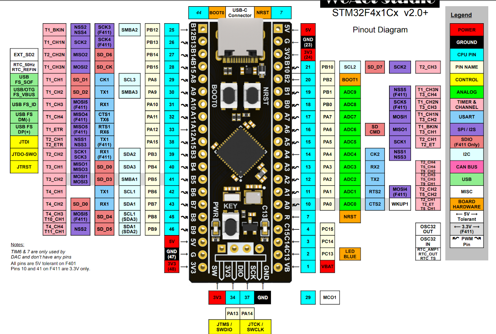
A processor from the ST32F4 series was chosen as the target, specifically the STM Black Pill board with the STM32F401 microcontroller which is based on the Arm® Cortex®-M4 architecture. The Black Pill board contains all necessary components for operation.
STM32 processors utilize a readout protection (RDP) that is divided into three stages. RDP level 1 (RDP-1) is the first level that restricts access to the microcontroller. With RDP-0 selected, no protection is active, i.e. the flash content of the microcontroller can be read out and the debug functions can be accessed. With RDP-1, the readout protection is active for the program flash, but the RAM of the microcontroller can still be accessed for debugging purposes. With RDP-2 selected, the microcontroller is completely closed. It is possible to switch from RDP-1 to RDP-0, but the program flash will be deleted. Switching from RDP-2 to RDP-1 is not supported by the microcontroller. The level of the readout protection can, for example, be set or read via the STM32CubeProgrammer.
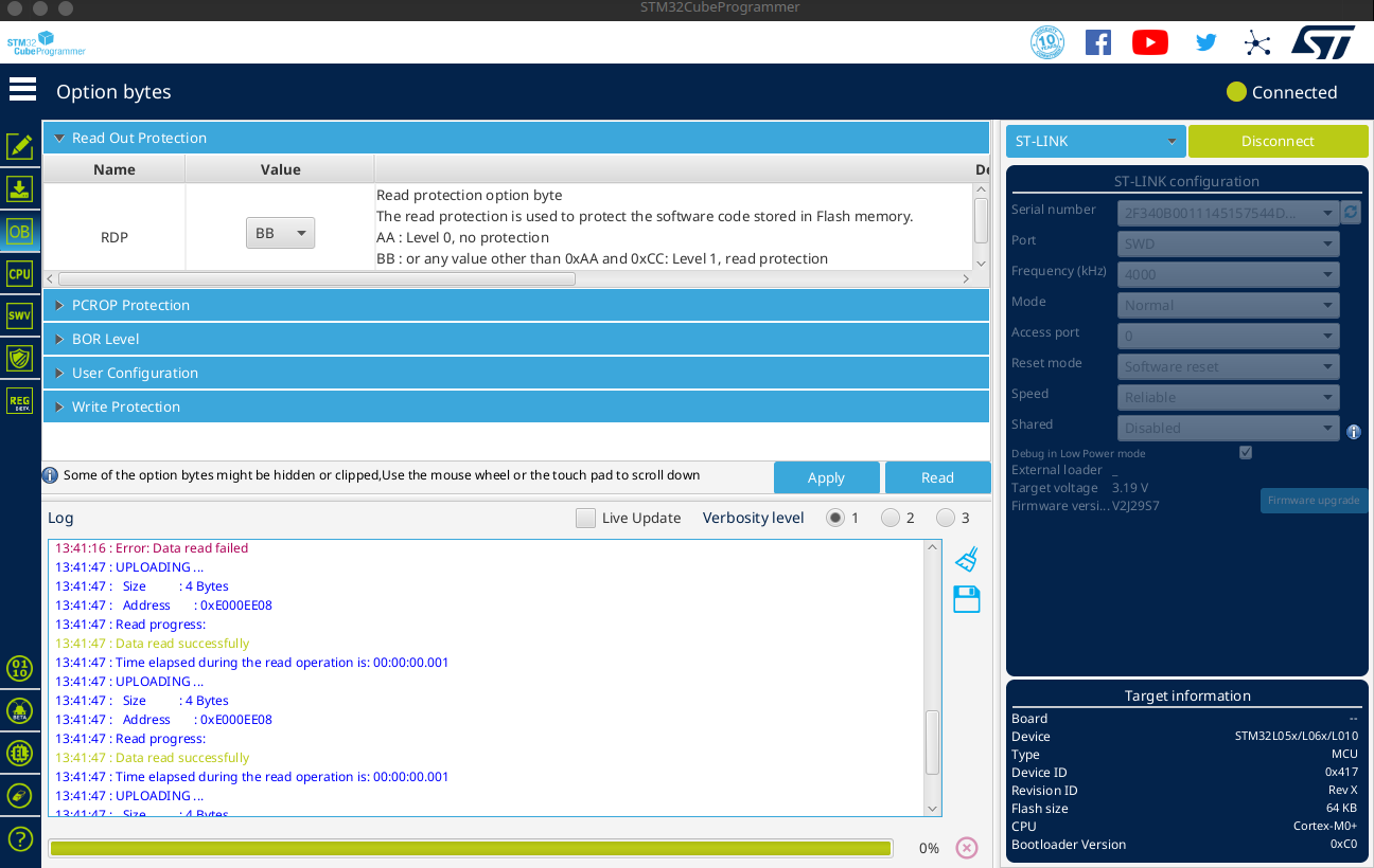
Due to the special values of the option bytes and the fact that the register values are redundant, a glitching attack is correspondingly unlikely. Switching from RDP-2 to RDP-1 is more likely, as only one bit (and the complementary bit in the redundant register) needs to be changed to activate RDP-1. The change from RDP-1 to RDP-0 is very unlikely since exactly the value 0xAA and the value 0x55 in the complementary register must be hit.
The glitch is inserted at one of the voltage regulator capacitors ('VCAP' pin). In order to achieve good results, the capacitor have to be removed from the board.

The following setup was selected to glitch the microcontroller.
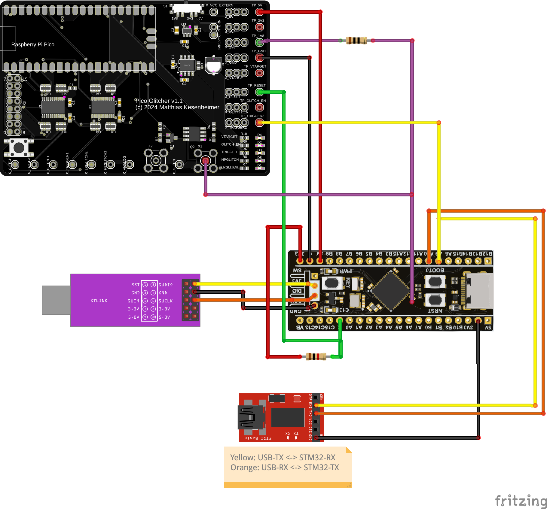
The colors of the connections encode these signals:
- red: Voltage supply of the Black Pill board (5V)
- purple: 1.8V voltage supply to the 'VCAP' pin decoupled with a 10 Ohms resistor and glitch input. The 1.8V voltage supply via the resistor is needed to get a stable voltage on the 'VCAP' pin.
- yellow: TX line to the STM32 microcontroller.
- orange. RX line to the STM32 microcontroller.
- also yellow: Trigger line, connected to the TX line to the STM32 microcontroller. If 0x11 (memory read command) is transmitted, the trigger is set.
- geen: Reset line to reset the microcontroller.
Additionally, an oscilloscope is connected to the TX line and the 'VCAP' pin (glitch line).
A simple test program was flashed onto the microcontroller. The sole purpose of this programme was to demonstrate a successful glitch.
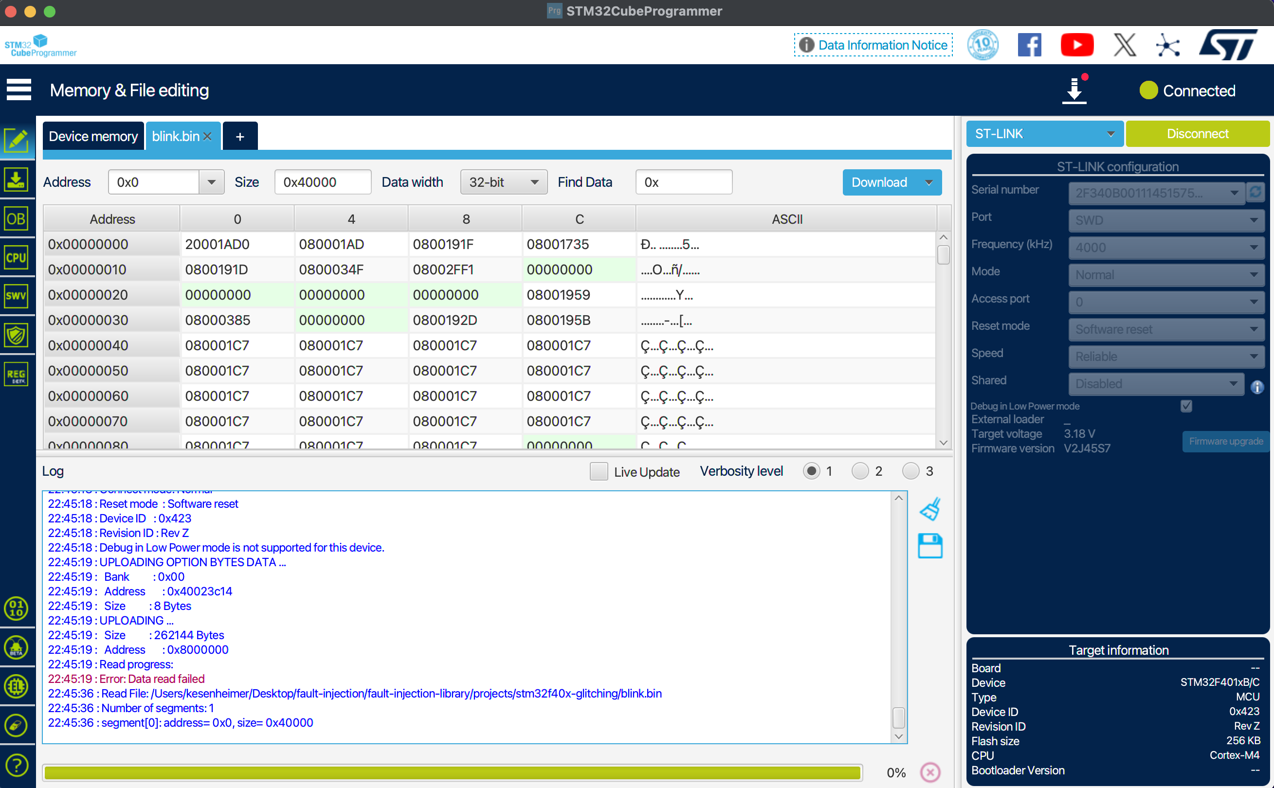
The bootloader of the STM32 processors offers a specific option for reading out the program flash. The bootloader mode is activated when the 'BOOT0' pin is connected to VCC. This can be done by pressing the 'BOOT0' switch on the Black Pill board, or by shorting the 'BOOT0' pin to VCC.
To read the program memory, a series of commands must be sent to the processor in bootloader mode via UART, which instruct the processor to return parts of the flash memory (see STMicroelectronics: USART protocol used in the STM32 bootloader). Among other things, the 'read memory' command is sent to the processor via UART, i.e. the byte 0x11. The glitcher is configured in such a way that it triggers as soon as byte 0x11 is recognized on the TX line. As the transmission of a second checksum byte requires additional 80µs, the interesting range begins at a 'delay' of 80,000ns and ends as soon as the bootloader sends the acknowledgement approximately 20-40µs later. In practice, it turns out that a range from 95,000ns to 125,000ns must be scanned. The duration of the glitch is selected just short enough so that the microcontroller is not reset ('brown-out') and long enough so that the glitch also has an effect. A 'length' of 25 to 35ns turns out to be good.
The script to perform the glitch can be found in the fault-injection-library and is typically run with the command:
python stm32f4-glitching.py --target /dev/tty.usbserial-A50285BI --rpico /dev/tty.usbmodem11101 --power /dev/tty.usbserial-10 --delay 95_000 125_000 --length 25 35
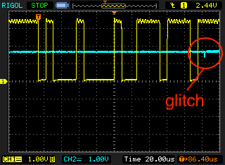
In the following figure, the glitch is barely visible after the bytes 0x11 and 0xee are sent via UART.
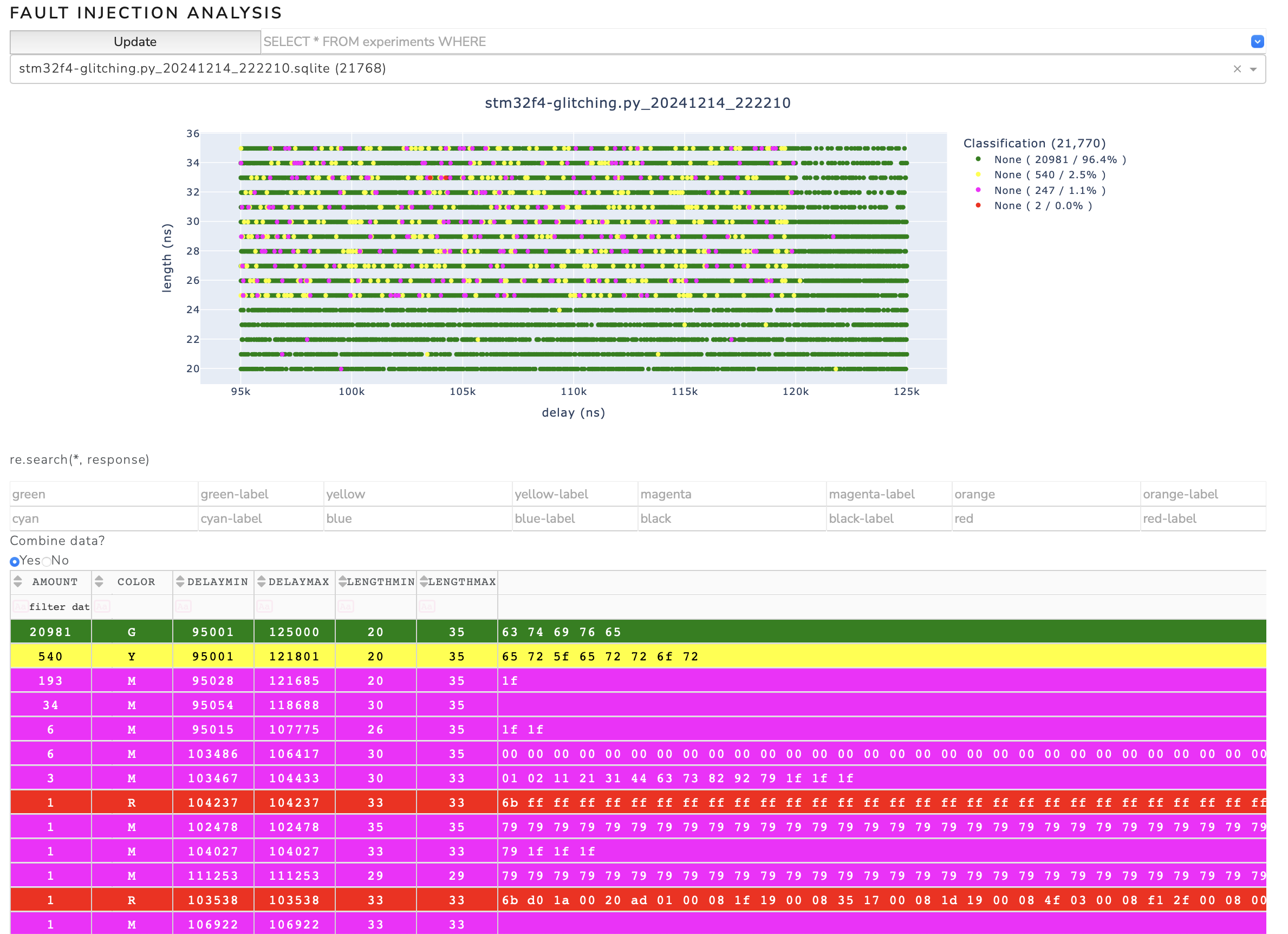
A successful glitching campaign can be seen in the following figure. Successful glitches were found around the parameter point (104,000ns, 33ns), for example.
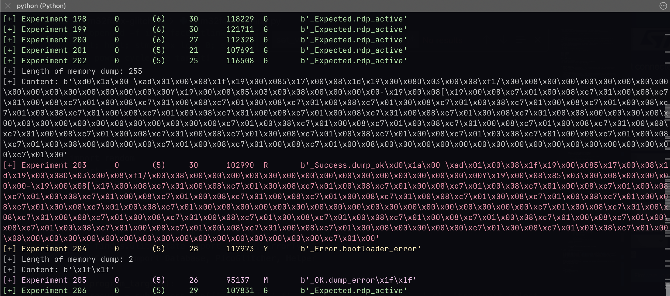
A status message is printed with the memory content if a successful glitch was found.
Things that can and will go wrong
Problem 1: Flash is sometimes completely erased
In addition to the memory read command, the bootloader also offers the memory erase command. If this function is accidentally triggered by a glitch, the entire flash content of the microcontroller is erased. This can happen up to once every 100,000 attempts. Interesting data (such as the firmware) is of course lost in that case.
Problem 2: PCROP protection
It can also happen that the SPRMOD bit is set in the event of a glitch. This bit causes the bytes returned by the bootloader when reading the flash contents to be masked with 0x00. This means that the bootloader is in the correct path of the read memory routine due to the glitch, but any response from the bootloader will be replaced with a zero by a downstream instance in the microcontroller.
If the PCROP bit is set by mistake, the glitching process must be aborted and the entire flash reprogrammed. Interesting data (e.g. firmware) will be lost.
Continue reading
Continue reading about the Pico Glitcher and its capabilities, or how to attack various microcontrollers, here:
- The beginning of the Pico Glitcher
- The Pico Glitcher v2
- The Pico Glitcher v3
- Voltage multiplexing and parameter optimization
- Attacking the STM32F4 with the PicoGlitcher
- Attacking the Trezor One Crypto Wallet (new firmware)
- Glitching the Raspberry Pico with a Raspberry Pico
- Attacking the SMT32L051 with the Pico Glitcher
- Attacking the nRF54L15 with an Electromagnetic Fault Injection (EMFI) attack and the Pico Glitcher
- Voltage Glitching with the Pico Glitcher and Findus
- The Pico Glitcher on Youtube