Attacking the Trezor One Crypto Wallet (new firmware)
Glitching firmware versions v1.6.1 and newer
I am selling the PicoGlitcher on faultyhardware.de.
More links:
- The Pico Glitcher and findus (the software to control the Pico Glitcher) are open source: fault-injection-library
- Documentation of the Pico Glitcher and findus: fault-injection-library.readthedocs.io
- hackaday.io project page: hackaday.io/project/196357-picoglitcher
- The Pico Glitcher was featured on Hackaday: hackaday.com/2024/10/30/use-picoglitcher-for-voltage-glitching-attacks/
The Trezor One crypto wallet is one of the earliest and most popular hardware wallets for securely storing cryptocurrencies. It isolates private keys from internet-connected devices, providing strong protection against malware and remote attacks.
Voltage glitching, which involves briefly tampering with the device's power supply to induce faults, can be necessary if the owner of the device has forgotten their PIN for unlocking the crypto wallet. By precisely timing these glitches, we can bypass security checks and extract sensitive data, such as the wallets passphrase.
This article will explain how to attack the Trezor One crypto wallet with firmware versions v1.6.1 and newer, and how to get from read-out protection level 2 (RDP-2) to complete flash access. While a previous research from Kraken showed that it is possible to get complete flash access to the device, the flash layout is different for devices with legacy firmware version v1.6.1.
Prerequisites
The following tools and materials are needed for the attack:
- Pico Glitcher v2.1 or later
- ST-Link-V2 debug adapter
- An adjustable power supply (for example RD6006)
- Logic Analyzer (for example Dreamwave Logic Pro)
- QFP-64 STM32 adapter
- 4.7kΩ resistors
- SMA cables and connectors
- Jumper cables
- Optional: a breadboard
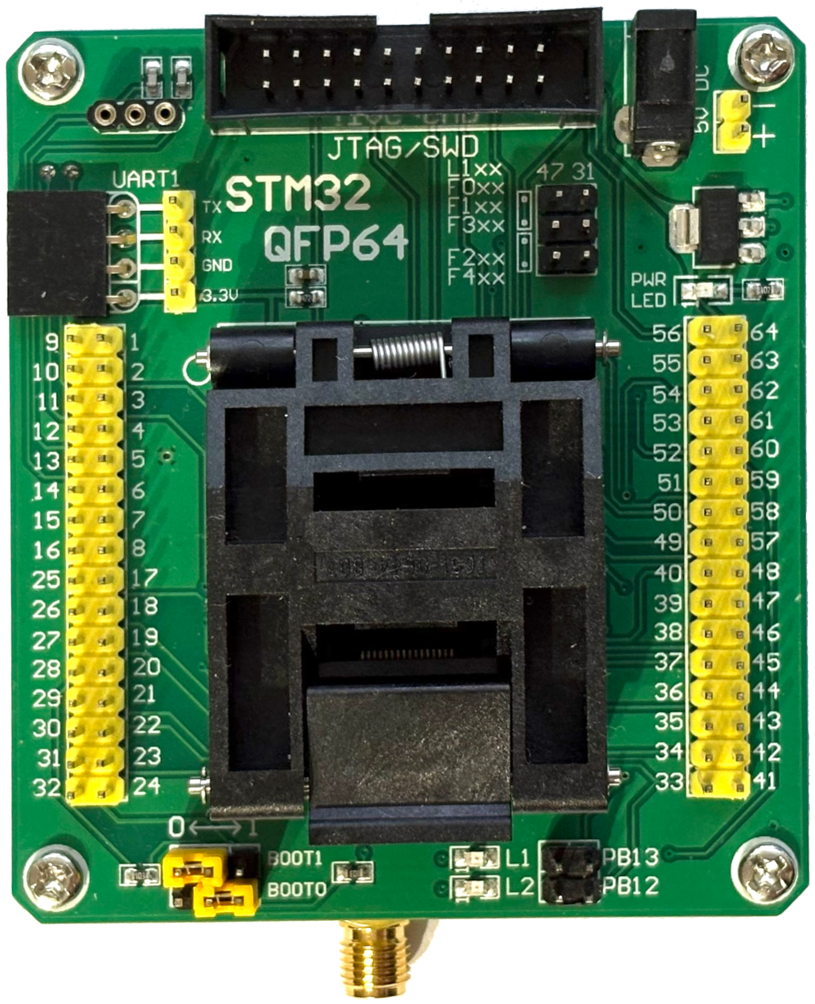
STM32-QFP64 adapter
For this attack, the STM32-QFP64 adapter from Waveshare proved to be very helpful. This adapter can be used to quickly swap out different targets and to easily access different pins of the chip. It also supplies power to the chip and enables different boot configurations to be selected via the jumpers.
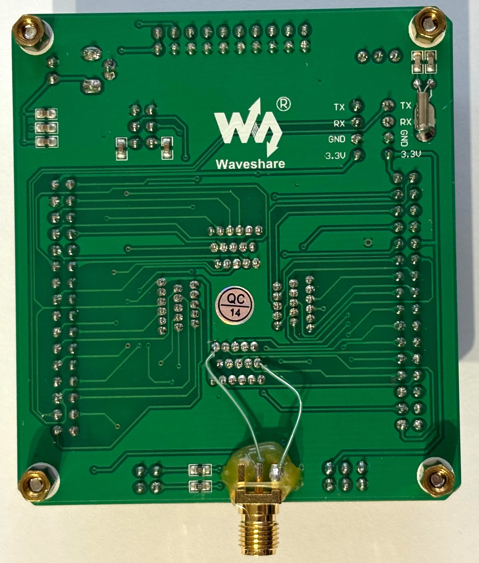
An SMA connector is soldered to the bottom of the board as shown below. This helps injecting the voltage glitches precisely and without much distortion. The SMA connector is held in place with a bit of glue.
Schematics
The complete setup for this attack is shown in the following figure.
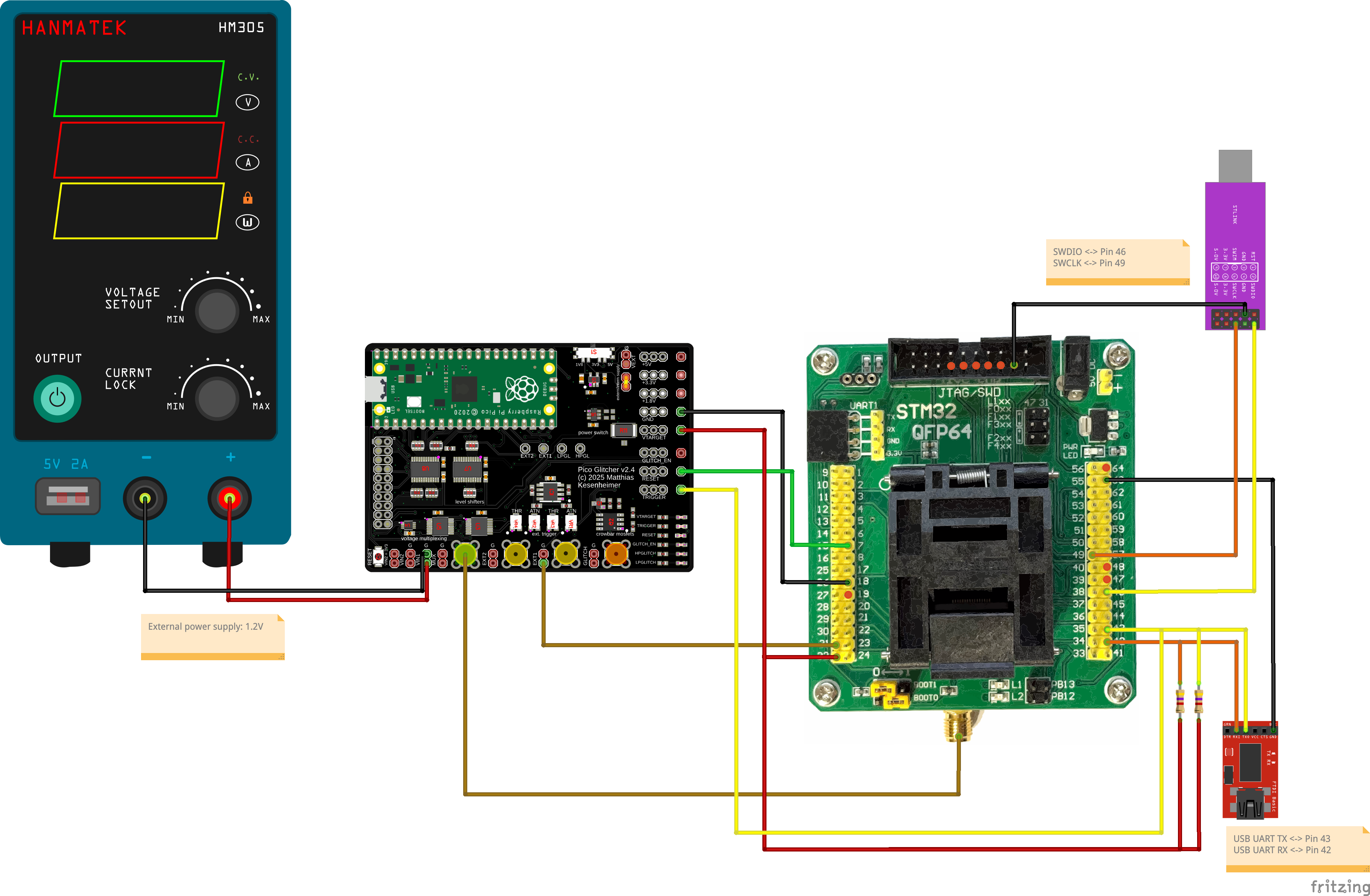
Additionally, the 'EXT TRIGGER' input of an oscilloscope is connected to the 'GLITCH_EN' output of the Pico Glitcher. We measure the voltage of the 'V_CAP' line ('MUX' output) on channel 1. The second channel of the oscilloscope can be used to measure either the 'RX' or 'TX' line.
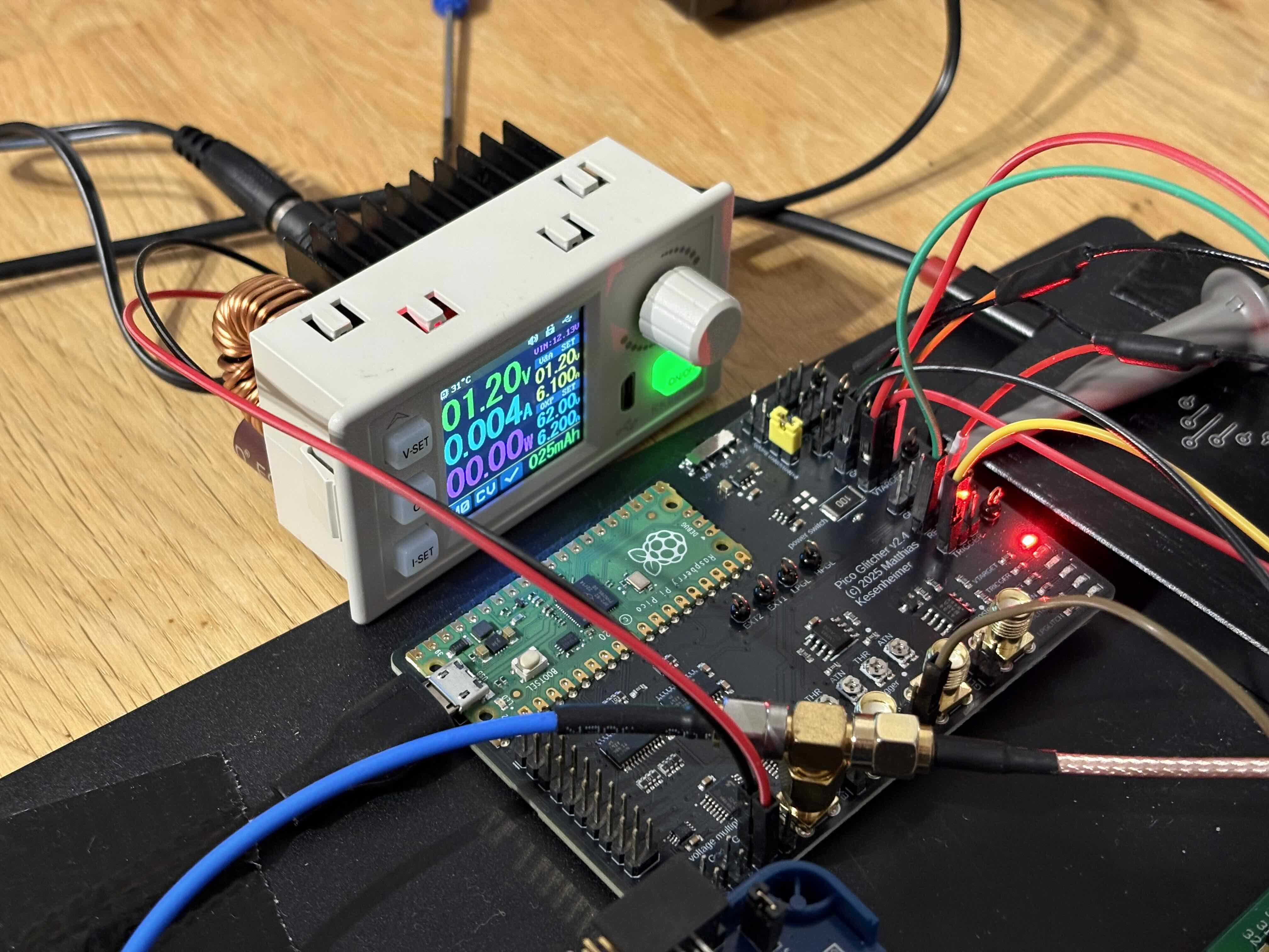
Images of the setup
The complete setup:
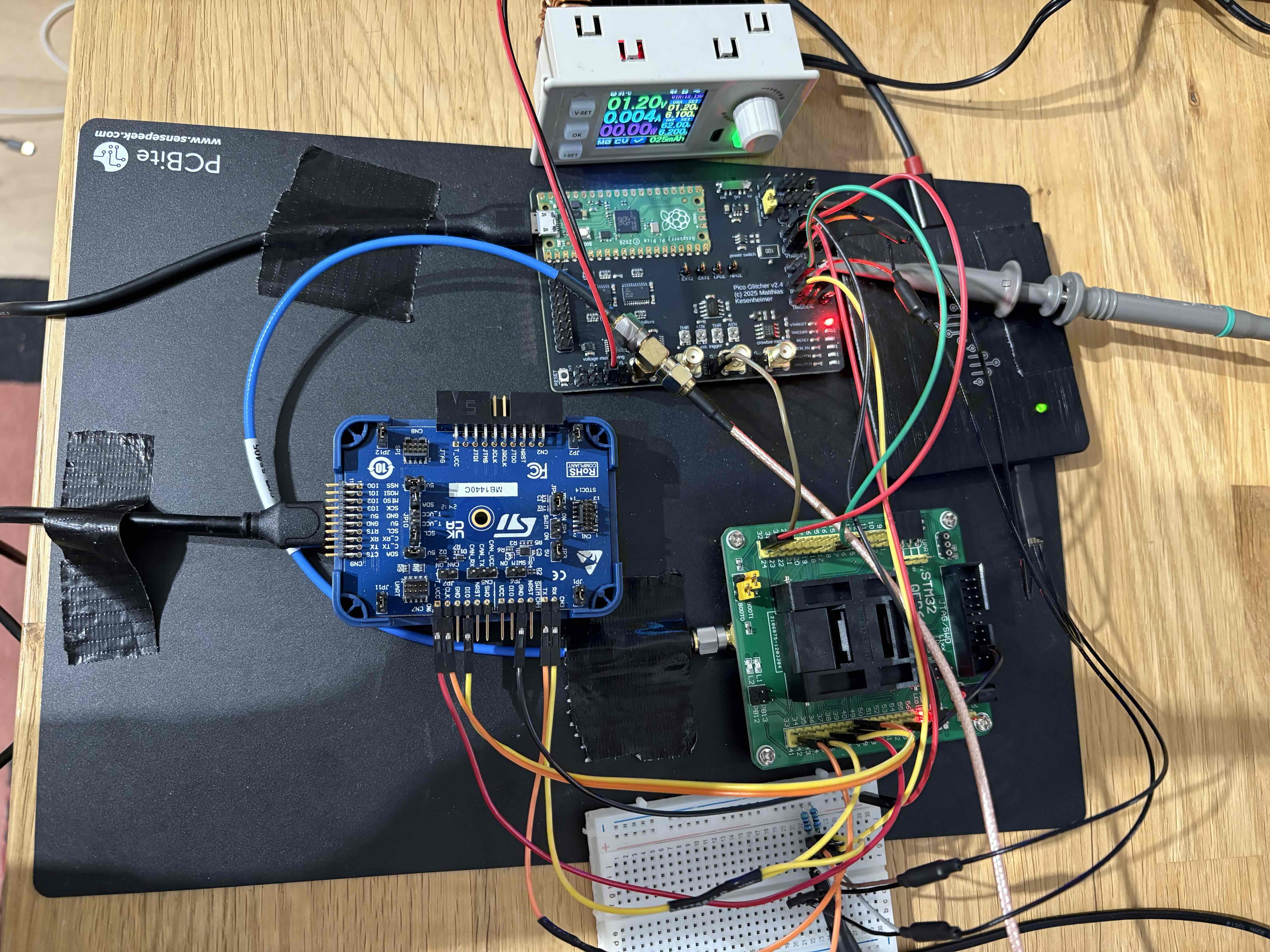
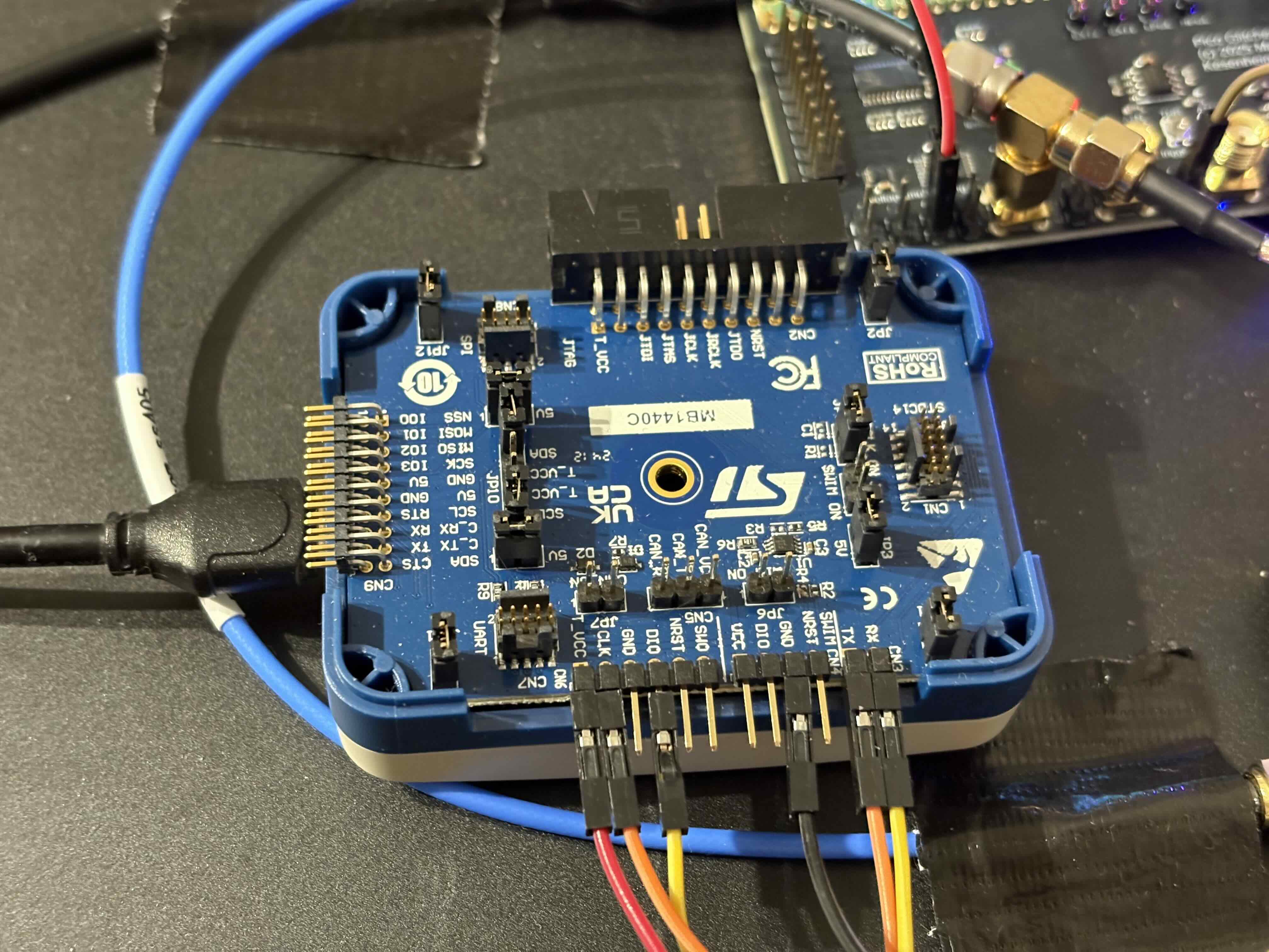
ST-LINK v3 with 'SWD' and 'UART' connected:
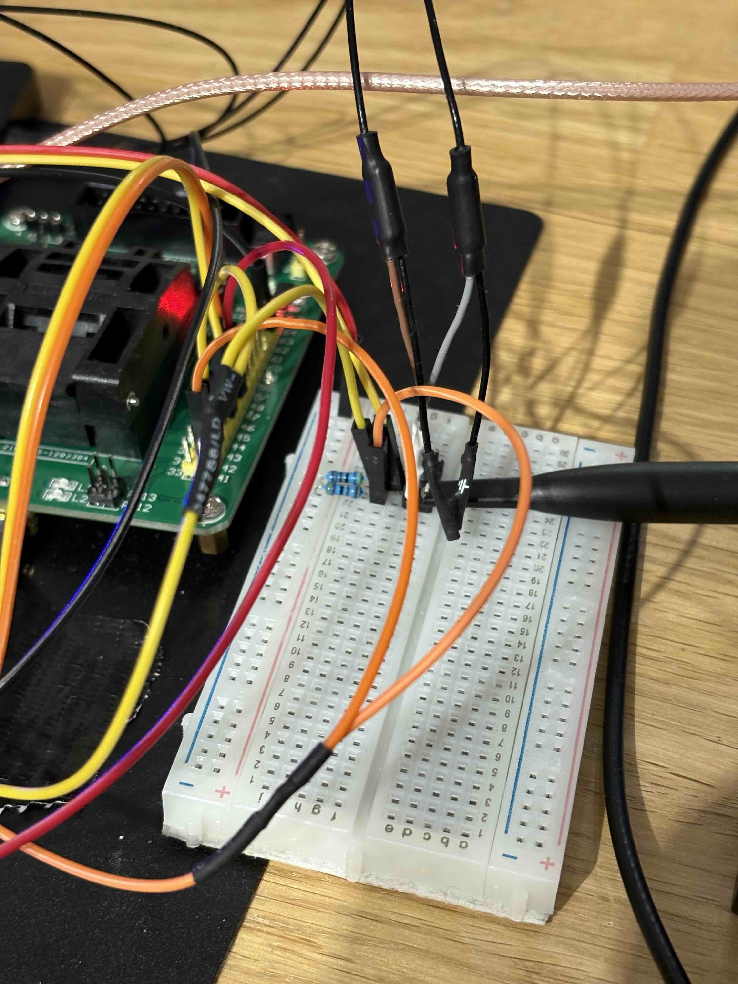
The '4.7kΩ' pull-up resistors on the 'TX' and 'RX' line:
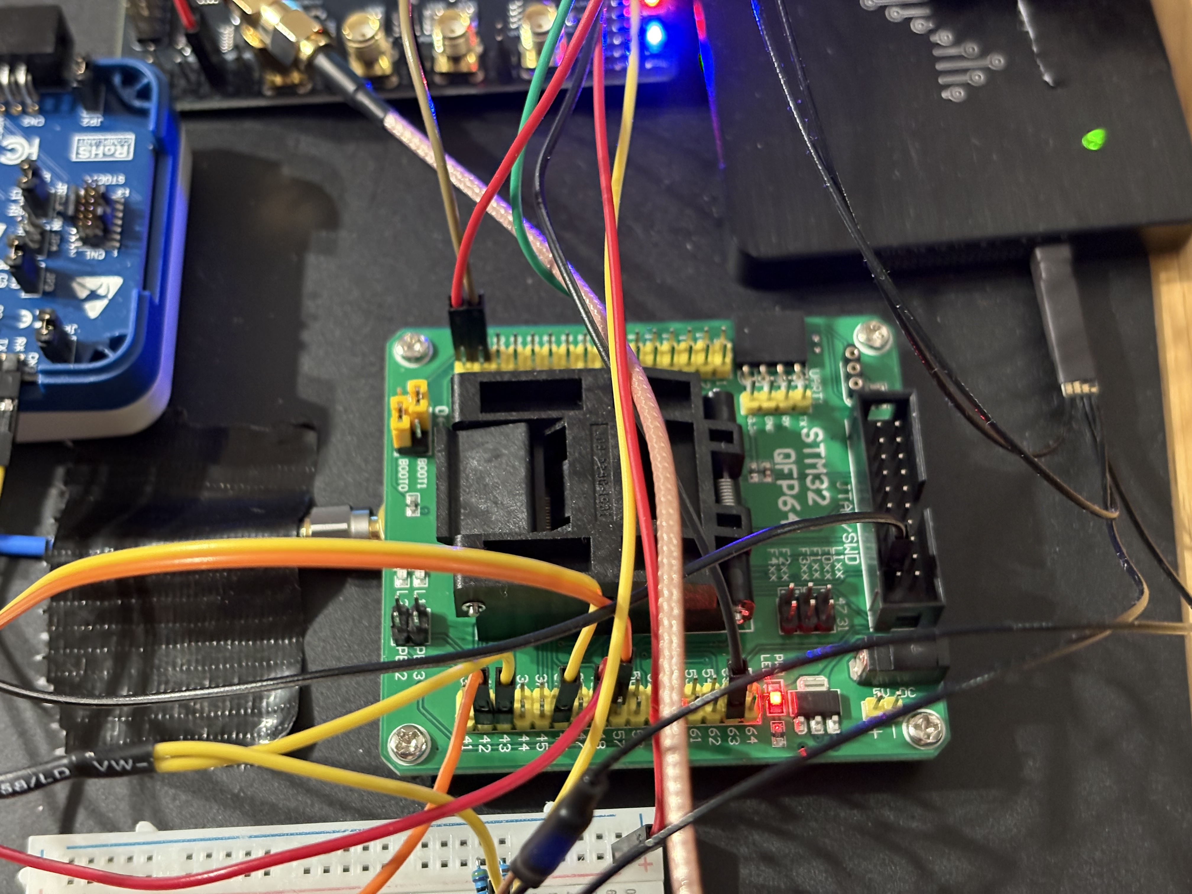
Connections to the STM23-QFP64 adapter:
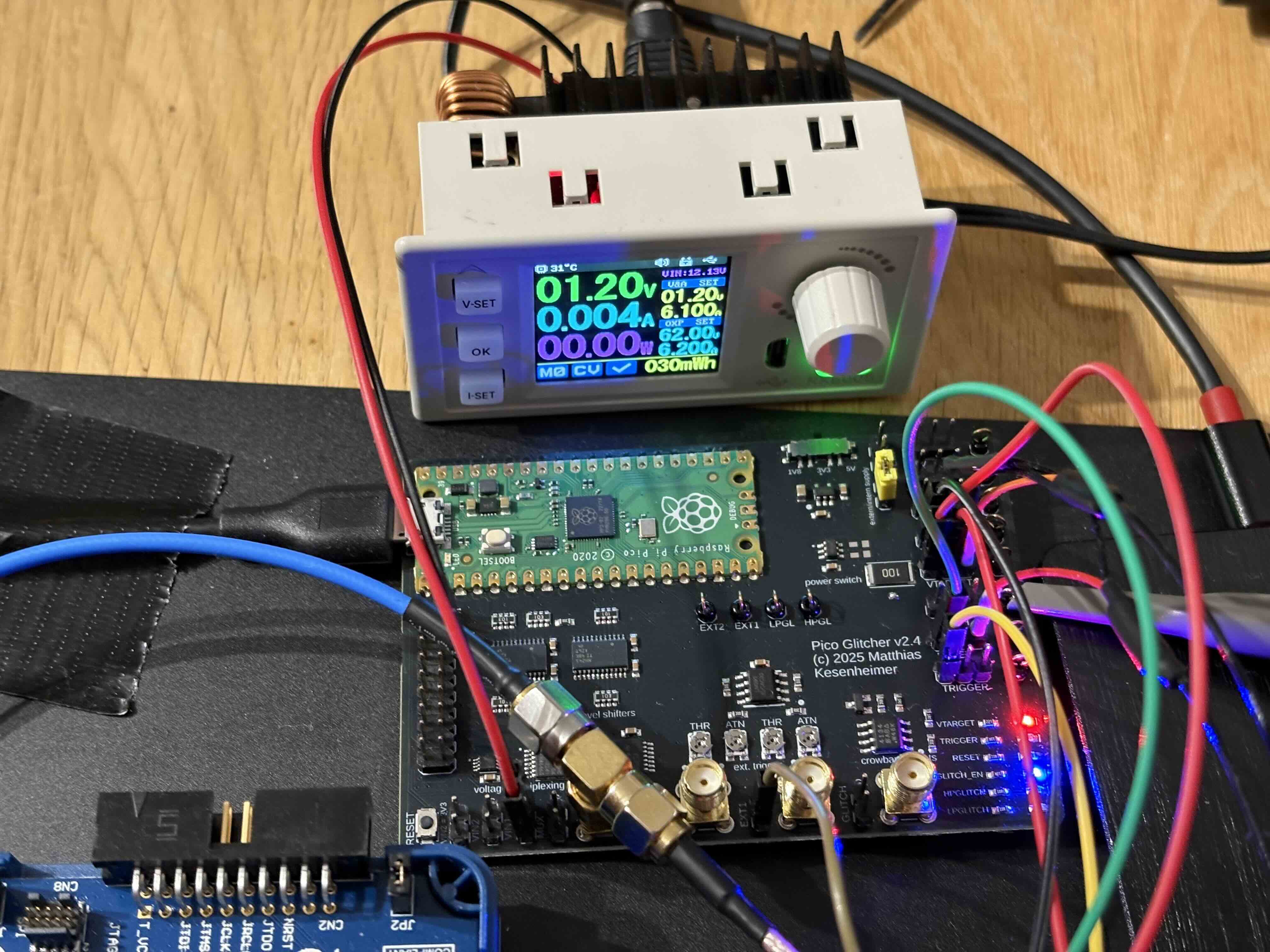
Pico Glitcher and external power supply connected to 'VIN1' (be sure to not exceed '1.2V'):
Voltage traces
We can now verify the startup sequence of the STM32F205 by measuring the voltage traces during startup:
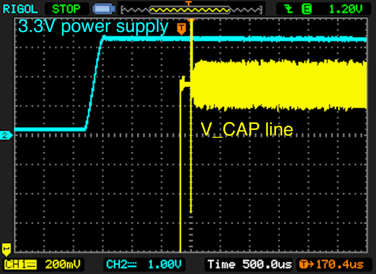
The level of the voltage supply should slowly rise in comparison to the voltage on the 'V_CAP' line. Furthermore, the voltage output on the 'VCAP' line is delayed approximately '150ms' after the device is powered on. Powering the device and measuring the voltage traces can be done with the command:
power-on --rpico /dev/pico-tty-device
Trigger condition
The trigger condition for stage 1 glitching (getting bootloader access) is measured on the 'EXT1' input. This input uses a configurable Schmitt trigger to generate a logical signal at a certain threshold. This threshold condition must be configured once and left untouched for the rest of the glitching campaign since changing it would also likely shift the 'delay' and 'length' parameters.
Glitching
Now everything is set up, we can start glitching the device. For this, the script 'stm32f2-bootloader-memread-mux.py' has been prepared. This script powers up the device, waits for the trigger signal on input 'EXT1', waits a given delay and emits a glitch of a certain length. Afterwards, it is tested if the bootloader responds properly via UART. If yes, the first stage has been successfully glitched and a downgrade from RDP-2 to RDP-1 was performed. The script continues with glitching the second stage.
In the second stage, the 'memread' command ('0x11ee') is sent to the device. The device checks if read-out protection is active. This check is glitched during the second stage of the script.
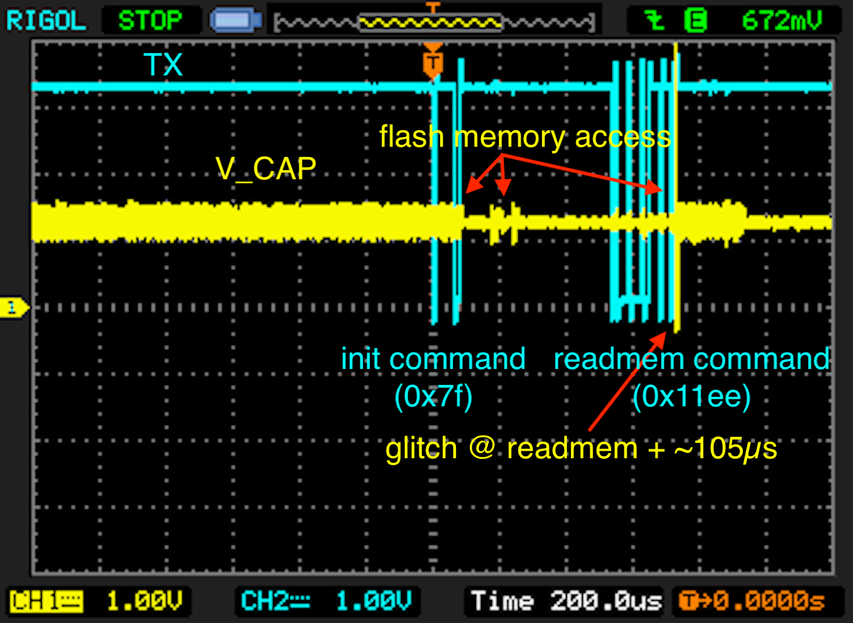
Stage 2 glitching (RDP-1 to RDP-0)
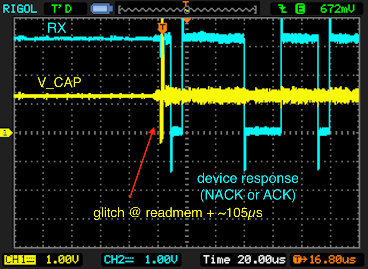
The glitch to downgrade from RDP-1 to RDP-0 is positioned approximetely '105µs' after the read memory command ('readmem = 0x11ee') and before the device acknowledges the command. This is verified with an oscilloscope.
The following figure shows the USB-UART transmit line (TX) and the voltage on 'V_CAP'. The glitch is emitted after the 'readmem' command ('0x11ee').
Next, the USB-UART receive line (RX) is shown. In this case, the device responds with two NACKs. The glitch is positioned before the device responds.
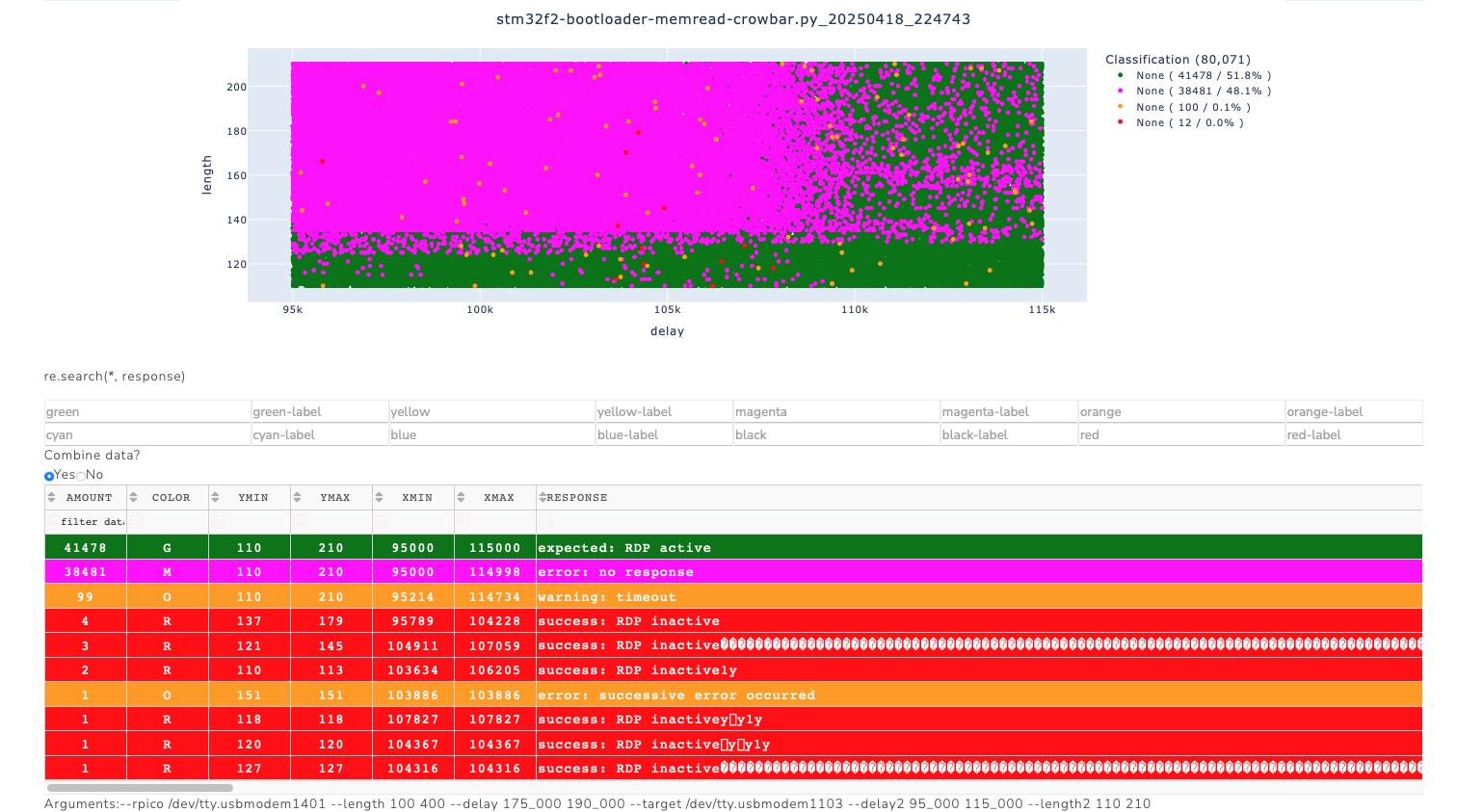
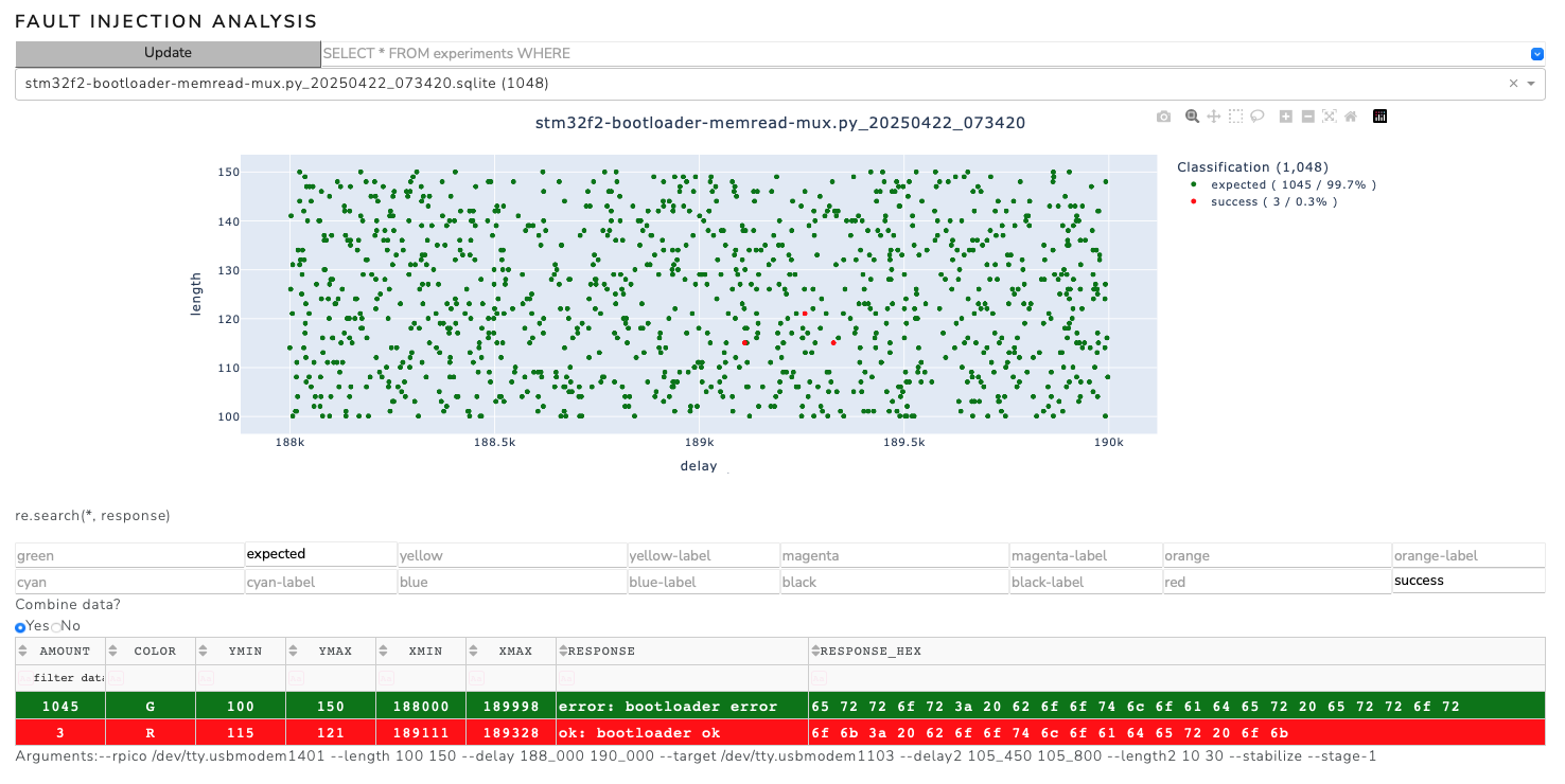
In order to get an overview of the parameterspace, a scan over the full range was performed. Positive events were found around '105µs' after the 'readmem' command.
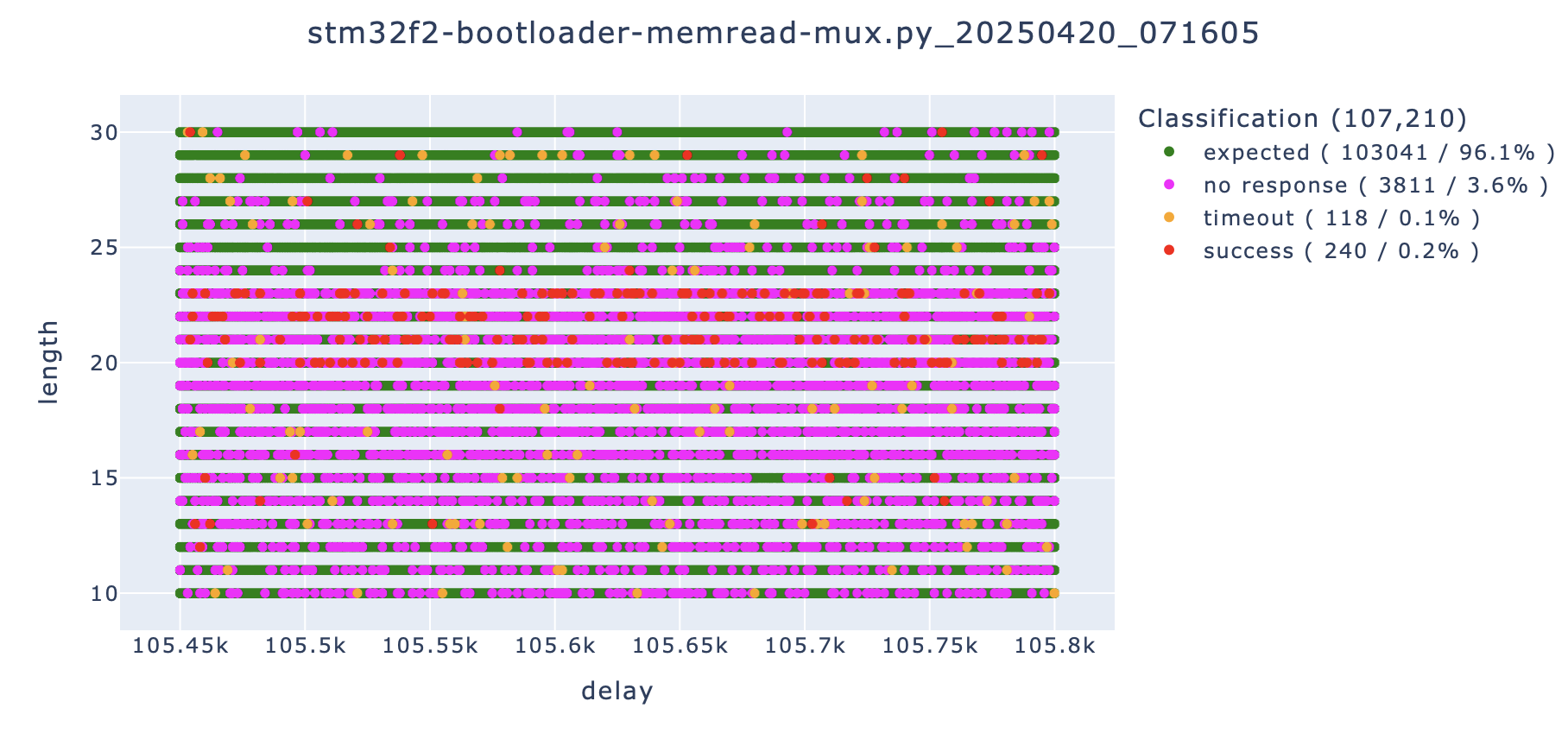
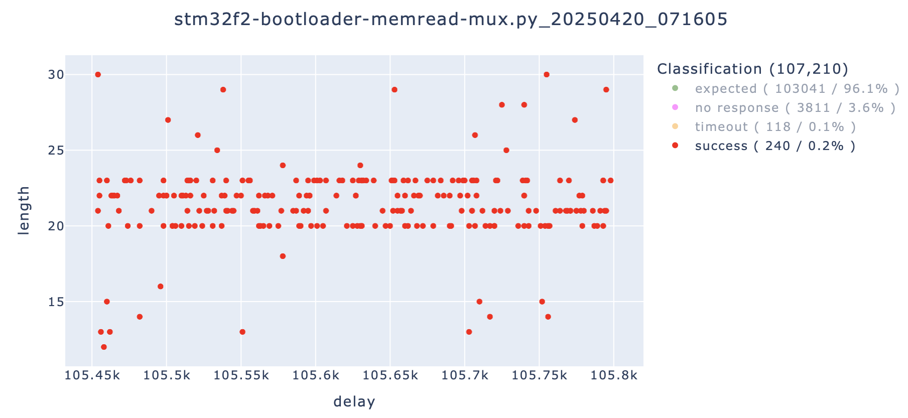
To optimize glitching and to be less invasive, the scan over the parameterspace was restricted in the next attempts. Good results were obtained with a delay in the range of '105.45µs' to '105.8µs' and a glitch length between '10ns' to '30ns'. A shorter glitch length proved to be better in this case as it seems to be less invasive. These parameters can be dependent on the Schmitt Trigger configuration, on the temperature or on the microcontroller itself. For best results, the parameters have to be tweaked for each target.
The following command was used to glitch the 'readmem' command. The parameters '--delay' and '--length' are not necessary at this stage and are ignored.
python stm32f2-bootloader-memread-mux.py --rpico /dev/pico-tty-device --length 0 0 --delay 0 0 --target /dev/stm32-tty-device --delay2 105_450 105_800 --length2 10 30 --stage-2
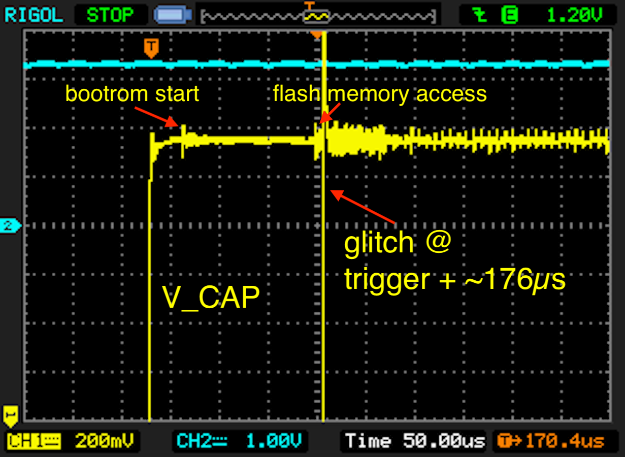
Stage 1 glitching (RDP-2 to RDP-1)
Glitching to obtain bootloader access is similar to Attacking the Trezor One Crypto Wallet (old firmware). However this time, the glitch is positioned '10µs' later, approximately '180µs' after the 'V_CAP' line rises.
The following command is used to search a bigger portion of the parameterspace for successful glitches. The parameters should be optimized in a later step to optimize success rate. The parameters '--delay2' and '--length2' are not necessary at this stage and are ignored.
Combining both attacks
The combined attack on a fully locked down target can be executed with the following command:
python stm32f2-bootloader-memread-mux.py --rpico /dev/pico-tty-device --length 110 130 --delay 188_900 189_500 --target /dev/stm32-tty-device --delay2 104_900 105_300 --length2 20 40
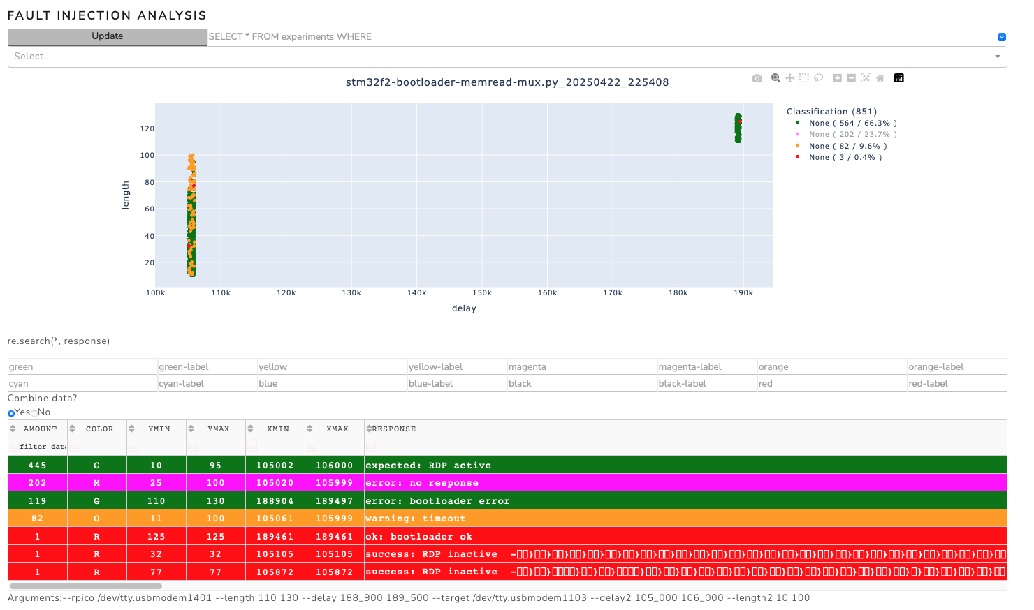
After a few attempts, the contents of the device's flash are displayed as the script's output.
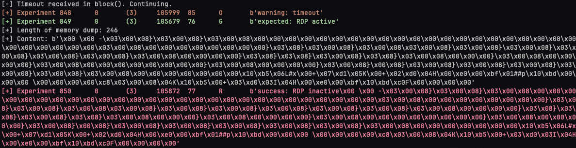
We can analyze the parameterspace for successful events and optimize accordingly.
Determining the address to read from
In most cases, it is unnecessary to download the entire contents of the device's flash memory, since we are only interested in the mnemonic passphrase or the PIN.
By analyzing the firmware of the device, the following memory offsets were found:
FLASH_BOOT_START = 0x08000000
FLASH_BOOT_LEN = 0x8000
FLASH_META_DESC_LEN = 0x100
FLASH_META_START = FLASH_BOOT_START + FLASH_BOOT_LEN = 0x08008000
FLASH_STORAGE_START	= FLASH_META_START + FLASH_META_DESC_LEN = 0x08008100
STORAGE_ROM = FLASH_STORAGE_START + sizeof(storage_magic) + sizeof(storage_uuid) = 0x08008100 + 4 + 12 = 0x08008110
Therefore, the mnemonic passphrase should be around memory offset '0x08008190', and the PIN around '0x08008290'. Hence, we need to perform two memory reads with 256 Bytes each starting from '0x08008190' to extract all secrets. This can be achieved by the following command:
python stm32f2-bootloader-memread-mux.py --rpico /dev/pico-tty-device --length 100 150 --delay 195_000 198_000 --target /dev/stm32-tty-device --delay2 105_000 106_000 --length2 10 50 --address 0x08008190 --size 0x1fe
Continue reading
Continue reading about the Pico Glitcher and its capabilities, or how to attack various microcontrollers, here:
- The beginning of the Pico Glitcher
- The Pico Glitcher v2
- The Pico Glitcher v3
- Voltage multiplexing and parameter optimization
- Attacking the STM32F4 with the PicoGlitcher
- Attacking the Trezor One Crypto Wallet (new firmware)
- Glitching the Raspberry Pico with a Raspberry Pico
- Attacking the SMT32L051 with the Pico Glitcher
- Attacking the nRF54L15 with an Electromagnetic Fault Injection (EMFI) attack and the Pico Glitcher
- Voltage Glitching with the Pico Glitcher and Findus
- The Pico Glitcher on Youtube