Attacking the Trezor One Crypto Wallet (old firmware)
Glitching firmware versions prior and equal to v1.6.0
I am selling the PicoGlitcher on faultyhardware.de.
More links:
- The Pico Glitcher and findus (the software to control the Pico Glitcher) are open source: fault-injection-library
- Documentation of the Pico Glitcher and findus: fault-injection-library.readthedocs.io
- hackaday.io project page: hackaday.io/project/196357-picoglitcher
- The Pico Glitcher was featured on Hackaday: hackaday.com/2024/10/30/use-picoglitcher-for-voltage-glitching-attacks/
The Trezor One is one of the earliest and most popular hardware wallets for securely storing cryptocurrencies. It isolates private keys from internet-connected devices, providing strong protection against malware and remote attacks.
Voltage glitching, which involves briefly tampering with the device's power supply to induce faults, can be necessary if the owner of the device has forgotten their PIN for unlocking the crypto wallet. By precisely timing these glitches, we can bypass security checks and extract sensitive data, such as the wallets passphrase.
This article will explain how to attack the Trezor One with firmware versions prior and equal to v1.6.0 and how to get from read-out protection level 2 (RDP-2) to RDP-1. With RDP-1 enabled, other attacks can be performed, for example reading out the chips SRAM to extact the passphrase. This attack has been shown previously by chip.fail and wallet.fail. However, as the issue of extracting the wallet's passphrase with SRAM access has been resolved in later firmware versions, this attack will not work on versions v1.6.1 and above. A later blog post will cover an attack that works on these devices.
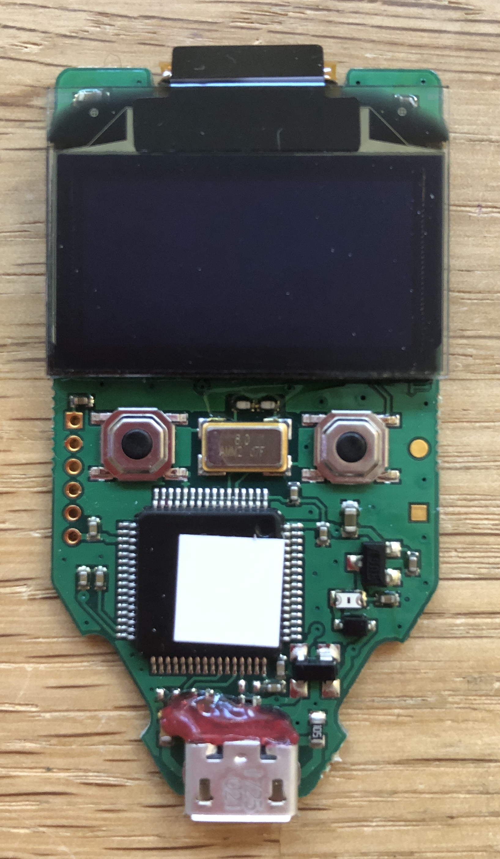
Preparations
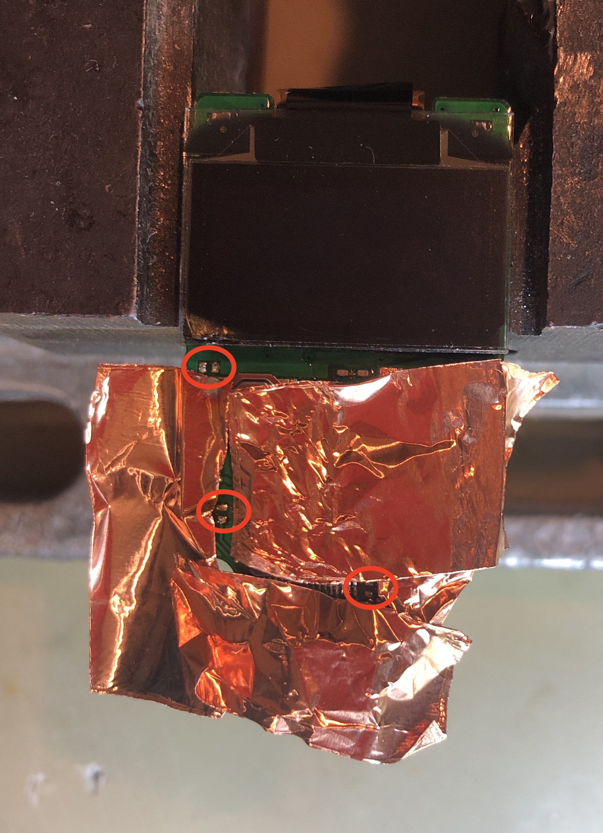
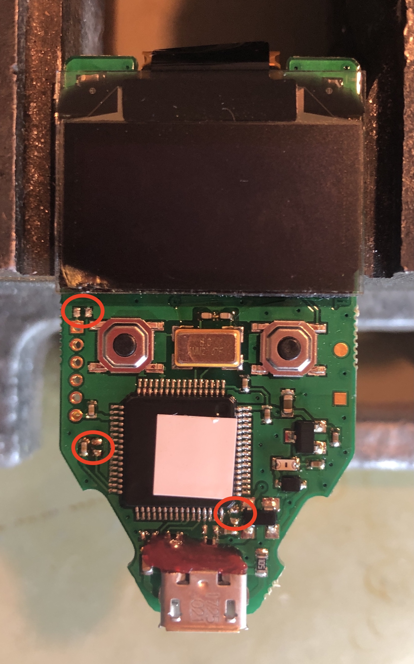
We start by covering delicate components with a metal foil and desolder the marked capacitors:
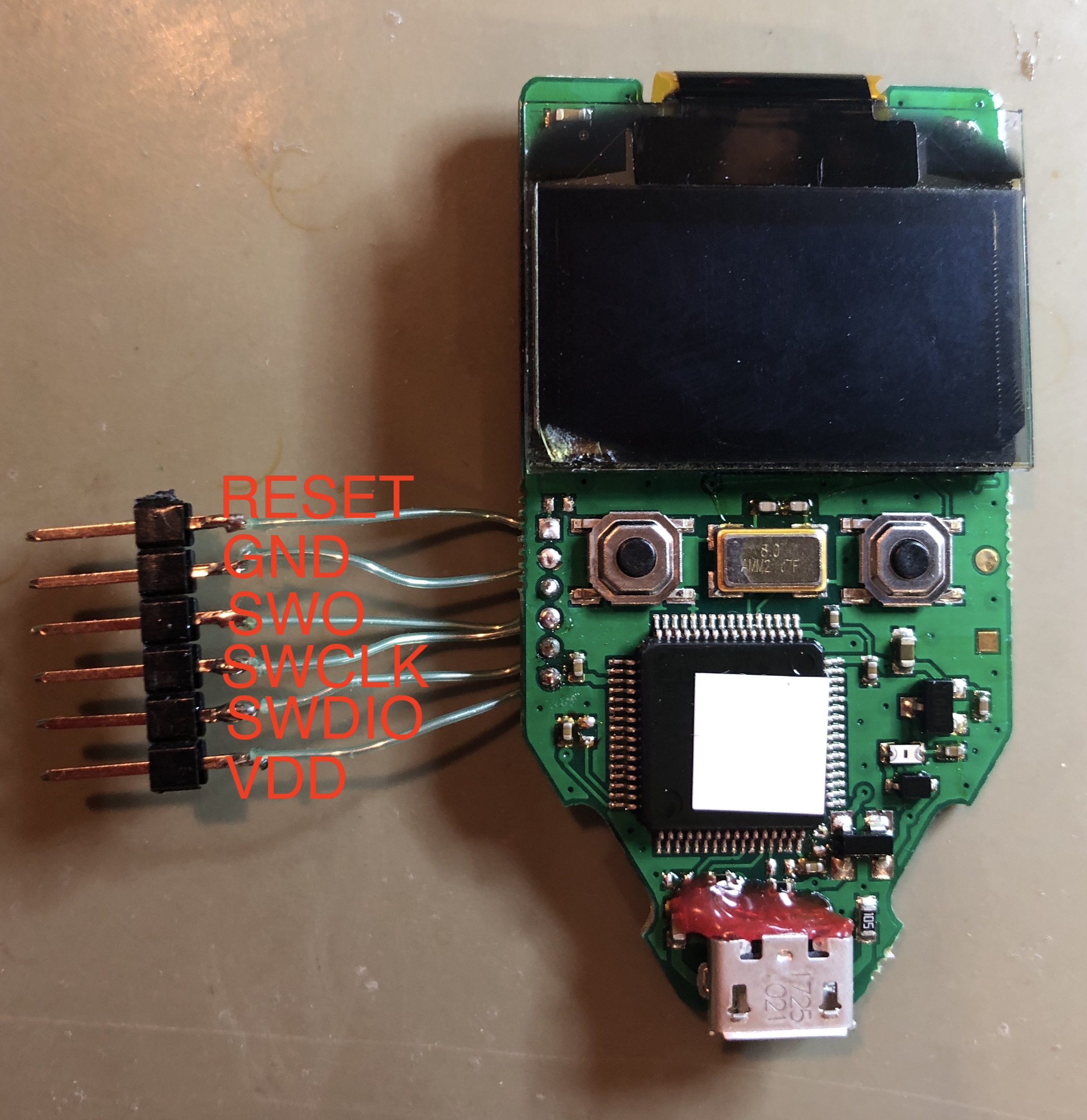
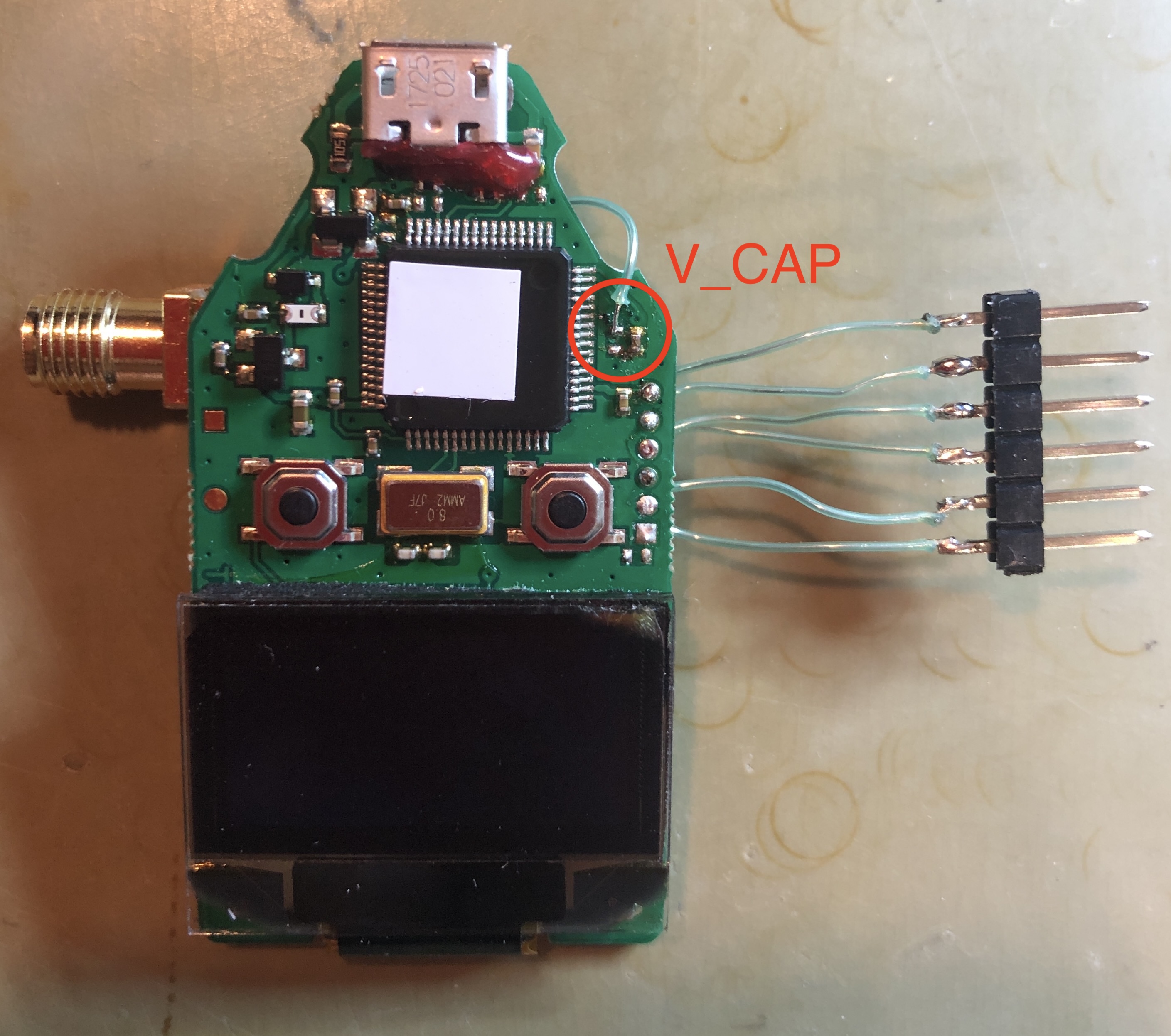
Then, a breakout pinheader is soldered to the Trezor One to get SWD access:
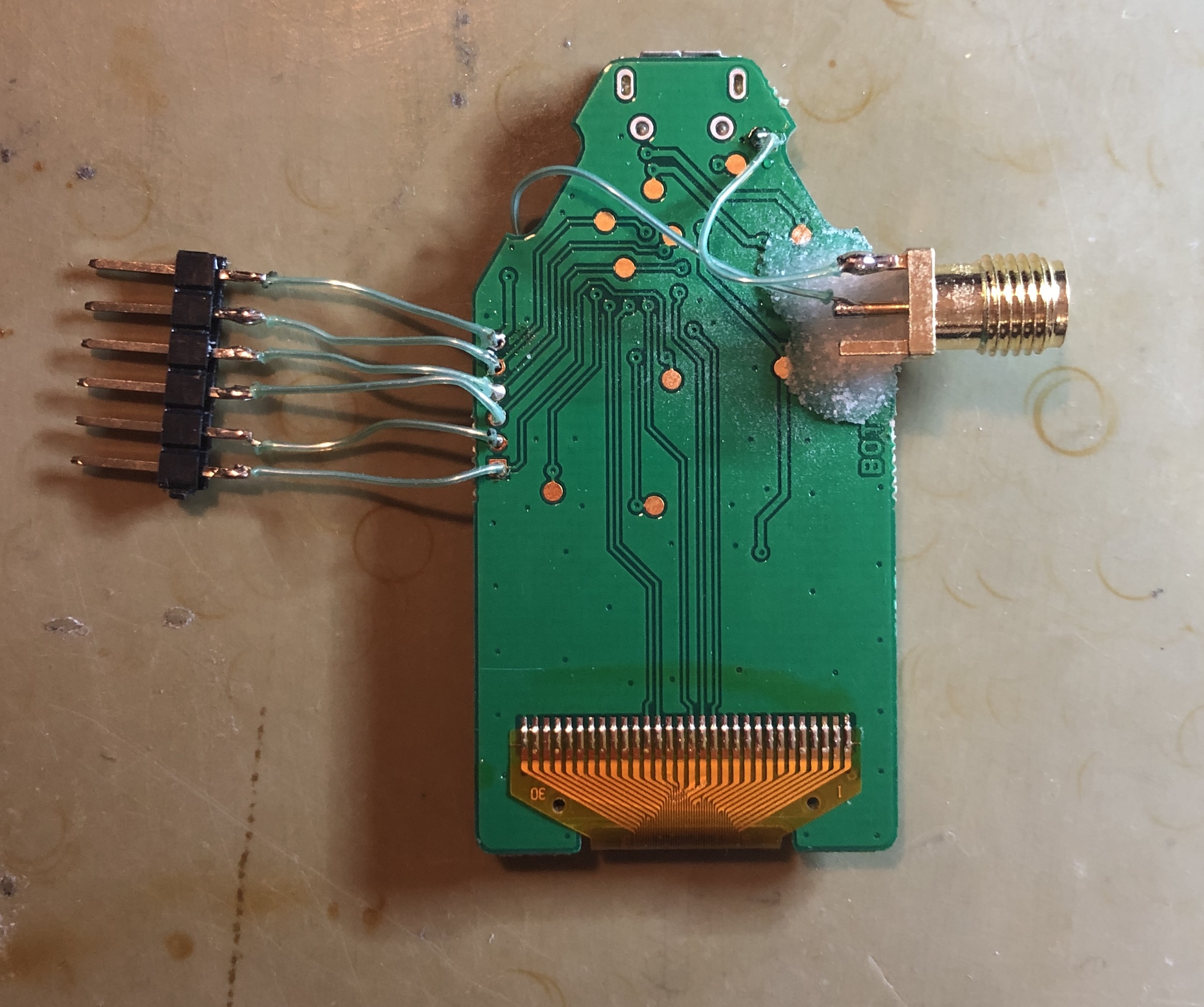
An SMA connector is glued to the backside of the device and connected the positive lead (middle pin) to the 'V_CAP' line and the negative lead to 'GND':
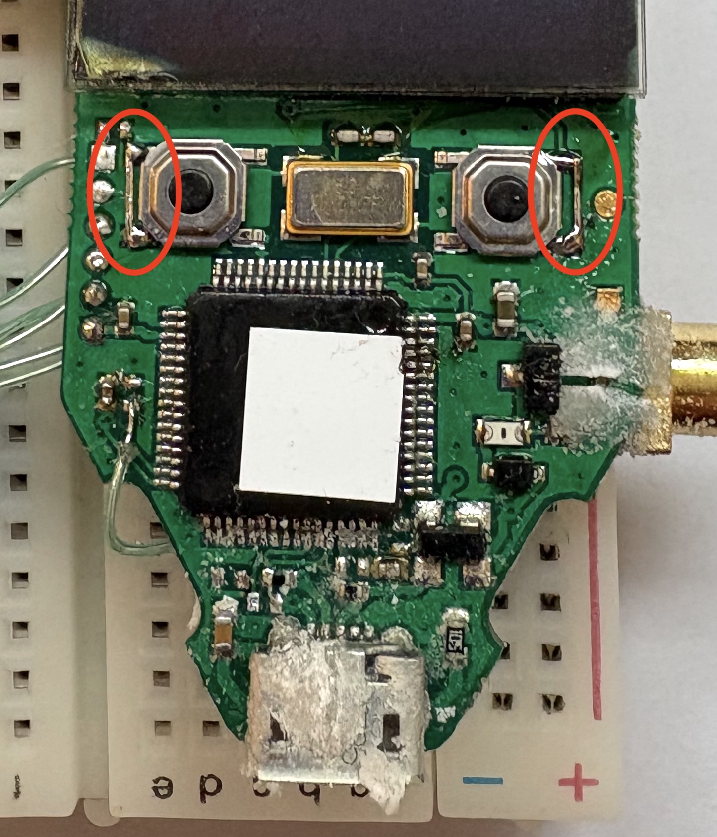
The two tactile switches are bridged. If the two buttons are pressed simultaneously, the Trezor One enters the bootloader mode for software updates. In this state, the recovery key is present in SRAM.
An ST-Link debug adapter is connected to the SWD lines, and the reset line to 'RESET', as well as the power lines to the Pico Glitcher. Then, the input 'EXT1' is connected to the crowbar glitch output 'GLITCH'. This is necessary to trigger on the rising-edge of the voltage on the 'V_CAP' line (green dupont cable in the following figure).
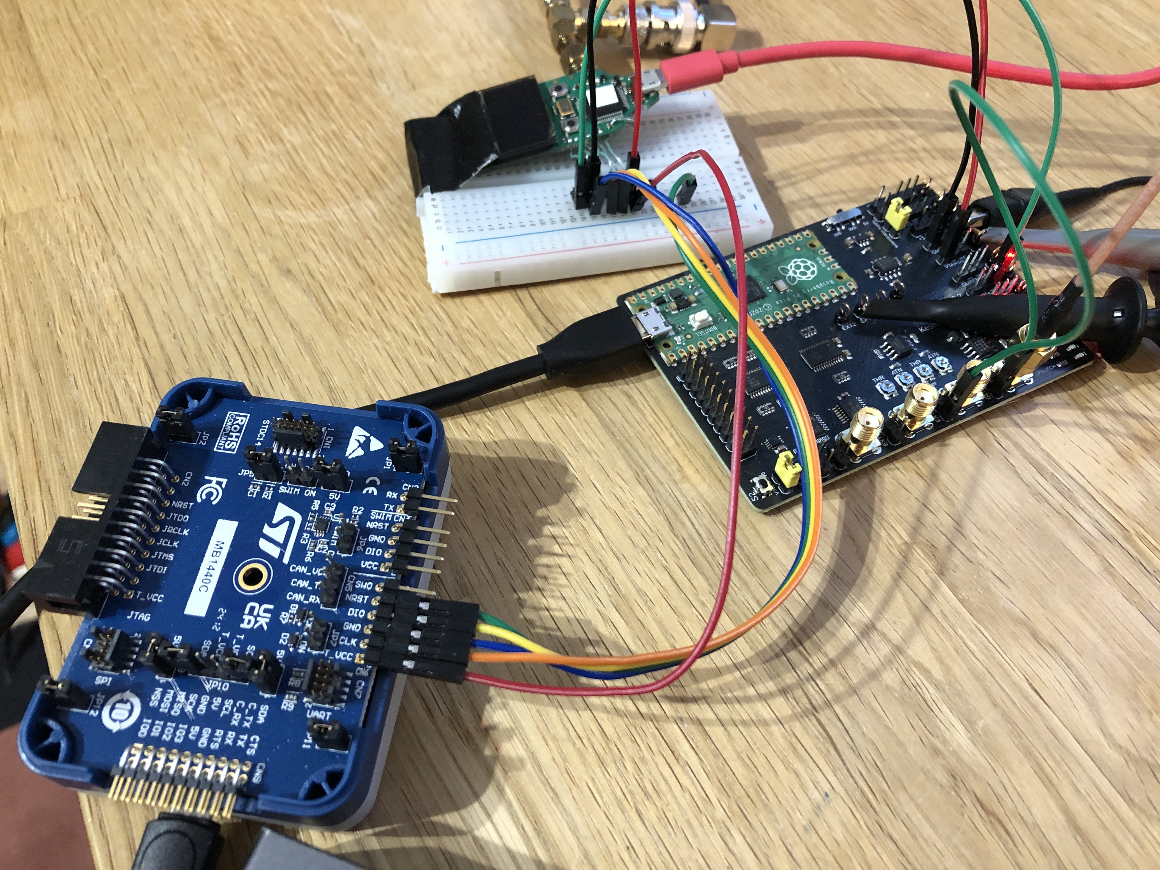
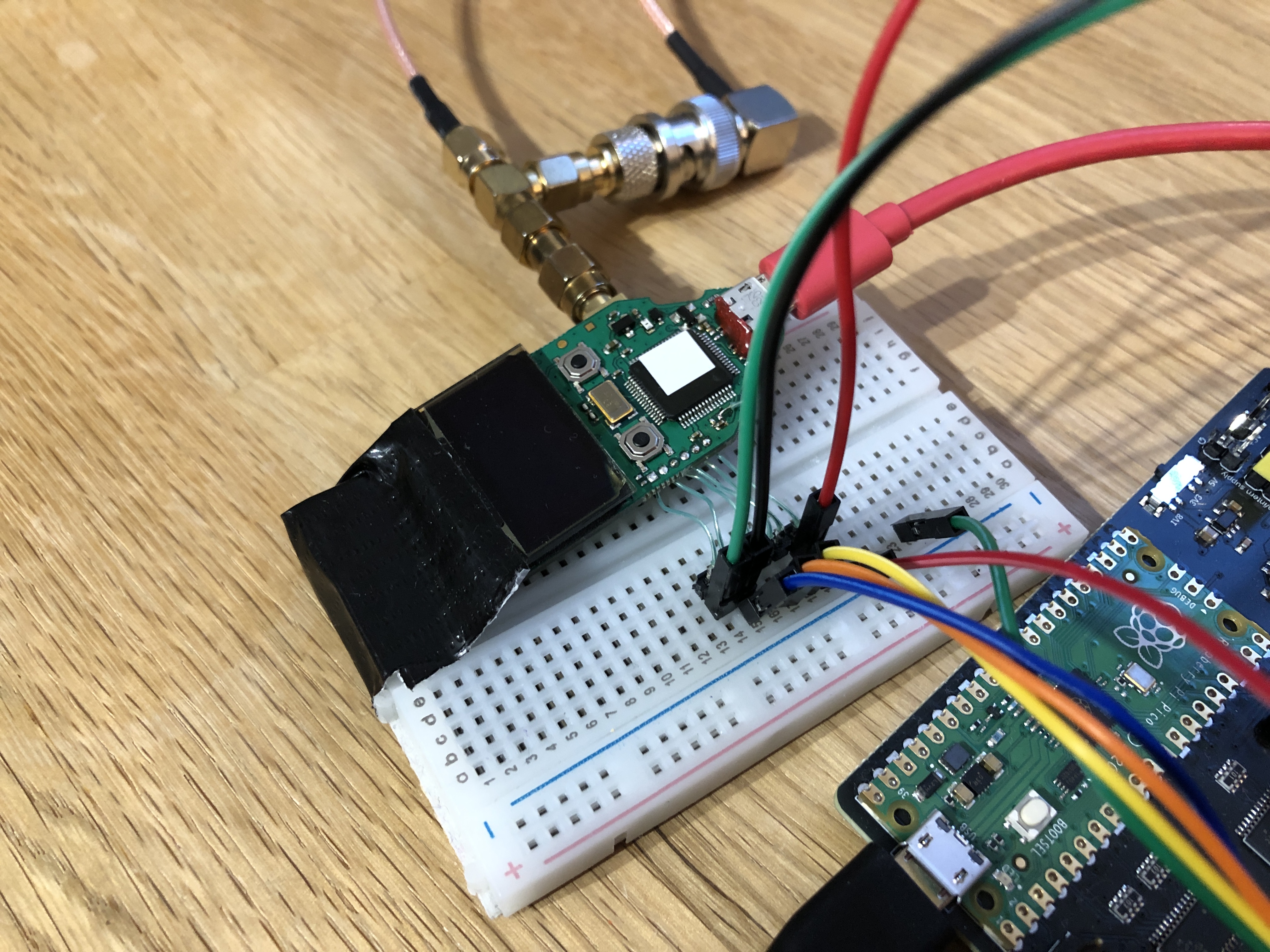
Channel 1 of an oscilloscope is connected to the 'VCAP' line via the SMA connector, channel 2 to the 'VTARGET' output and the external trigger input of the oscilloscope to the 'EXT1' hook.
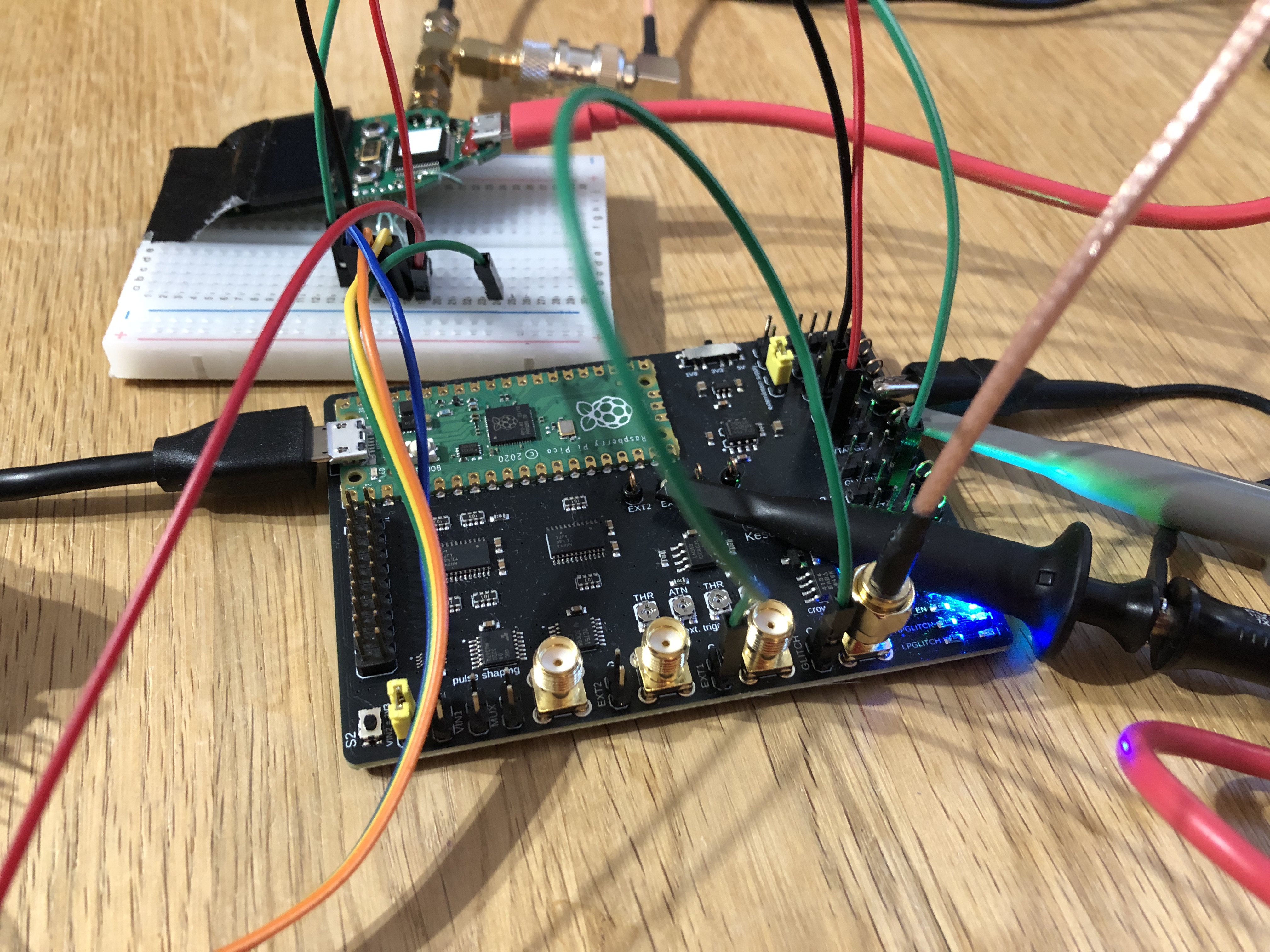
It is important not to connect the Trezor One to a computer via USB during glitching.
Voltage Traces
The startup sequence of the STM32F205 can now be verified by measuring the voltage traces during startup:
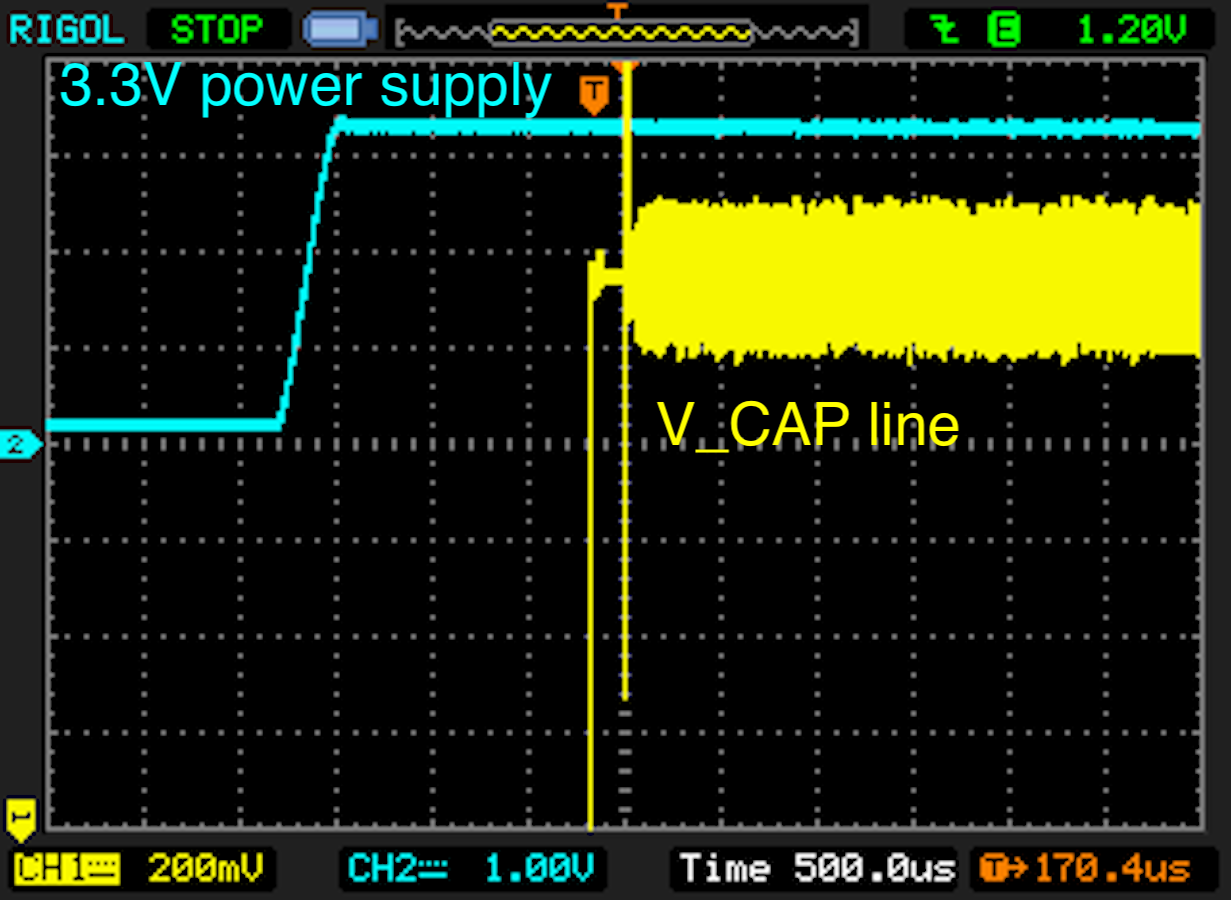
The level of the voltage supply should slowly rise in comparison to the voltage on the 'V_CAP' line. Furthermore, the voltage output on the 'VCAP' line is delayed approximately 150ms after the device is powered on. Powering the device and measuring the voltage traces can be done with the command:
power-on --rpico /dev/tty-device
Glitching
Now everything is set up, we can start glitching our device. For this, the script 'stm32f2-boot-debugger.py' has been prepared. This script powers up the device, waits for the trigger signal on input 'EXT1', waits a given delay and emits a glitch of a certain length. Afterwards, it is tested if memory can be read from RAM.
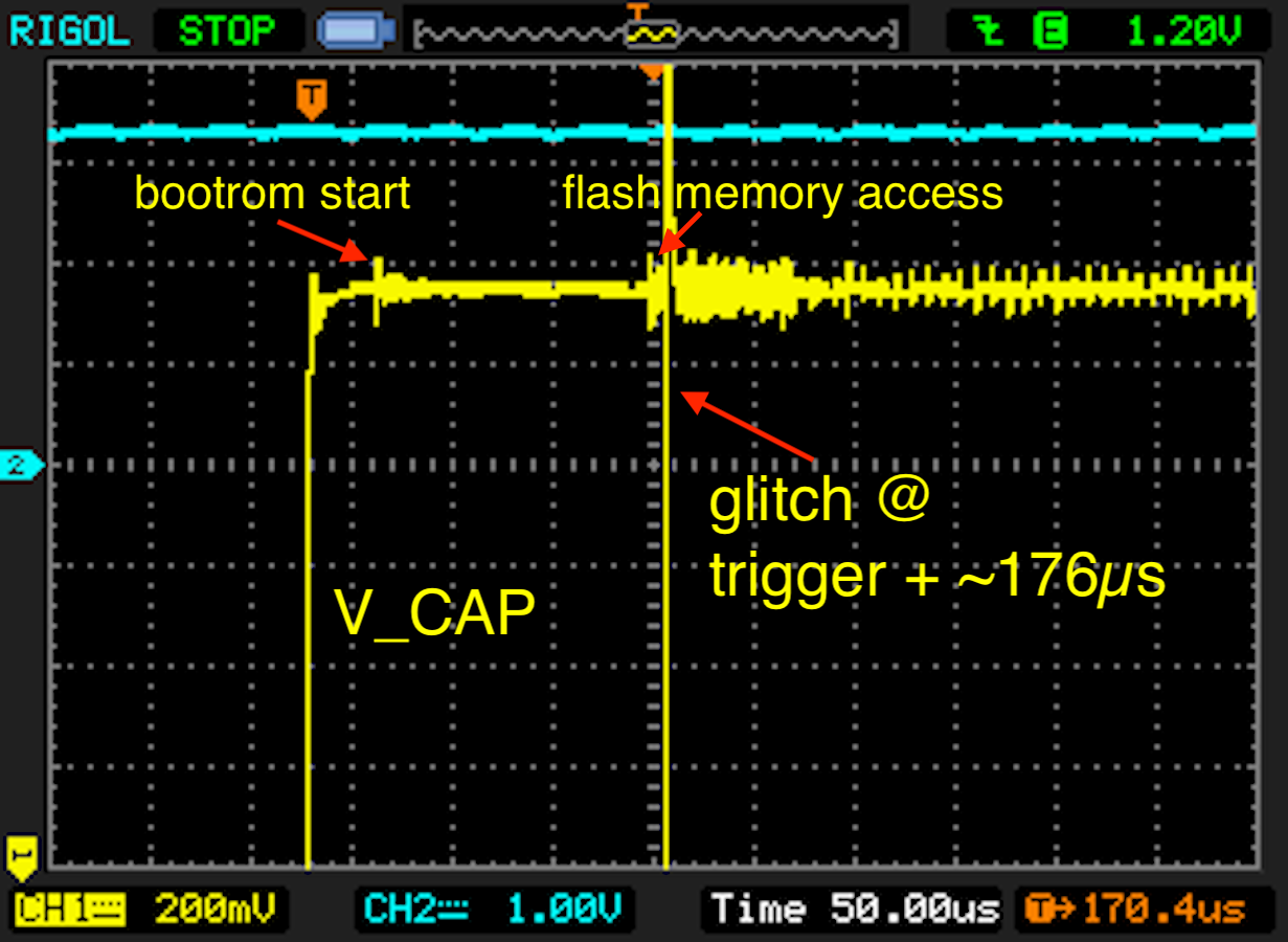
Successful glitches should be found about 176us after the 'VCAP' line comes up. We start by searching a wider parameter space and reduce the parameter space when the first positive events are observed. The glitch length is not critical, but in general shorter glitches are preferable.
python stm32f2-boot-debugger.py --rpico /dev/tty-device --length 100 500 --delay 175_600 176_700 --halt [--resume]
We can use the 'analyzer' from 'findus' to analyze the glitch parameters:
analyzer --directory databases --auto-update 60
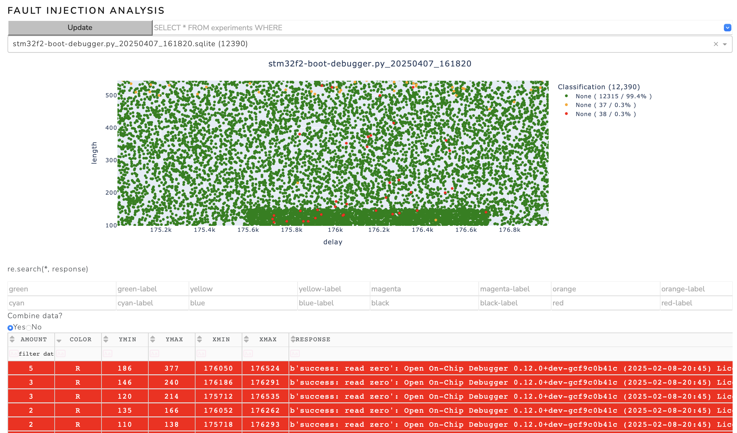
When the script is stopped (when a successful glitch is detected), further instructions are printed to the terminal:
[+] Experiment 158	12914	(3)	176526	126	R	b'success: read zero'
[+] Now connect the Trezor One via USB with your computer and go to the Trezor Suite app.
    Wait for the Trezor One to connect. Do not abort this script!
    If the pin input on the Trezor comes up, execute the following command to dump the memory:
    $ openocd -f interface/stlink.cfg -c "transport select hla_swd" -f target/stm32f4x.cfg -c "init; reset run"
    Connect to openocd via gdb or telnet:
    $ telnet localhost 4444
    $ arm-none-eabi-gdb
    (gdb) target remote :3333
    (gdb) monitor reset halt
    (gdb) continue
    Or dump the RAM as is with the following command:
    $ openocd -f interface/stlink.cfg -c "transport select hla_swd" -f target/stm32f4x.cfg -c "init; dump_image ram.bin 0x20000000 0x1fffffff; exit"
In this state, we can either try to dump the RAM contents:
openocd -f interface/stlink.cfg -c "transport select hla_swd" -f target/stm32f4x.cfg -c "init; dump_image ram.bin 0x20000000 0x1fffffff; exit"
Or we can connect to the device via telnet or gdb. First, a debug connection with openocd is initialized:
openocd -f interface/stlink.cfg -c "transport select hla_swd" -f target/stm32f4x.cfg -c "init; reset run"
Then we connect to the device via telnet:
telnet localhost 4444
Or GDB:
arm-none-eabi-gdb
(gdb) target remote :3333
(gdb) monitor reset halt
(gdb) continue
By dumping the RAM in this state, the recovery key should be visible in the dump. Observe the RAM dump with the 'strings' command:
strings ram.bin
Continue reading
Continue reading about the Pico Glitcher and its capabilities, or how to attack various microcontrollers, here:
- The beginning of the Pico Glitcher
- The Pico Glitcher v2
- The Pico Glitcher v3
- Voltage multiplexing and parameter optimization
- Attacking the STM32F4 with the PicoGlitcher
- Attacking the Trezor One Crypto Wallet (new firmware)
- Glitching the Raspberry Pico with a Raspberry Pico
- Attacking the SMT32L051 with the Pico Glitcher
- Attacking the nRF54L15 with an Electromagnetic Fault Injection (EMFI) attack and the Pico Glitcher
- Voltage Glitching with the Pico Glitcher and Findus
- The Pico Glitcher on Youtube