Pico Glitcher v3
A device to perform fault-injection attacks
I am selling the PicoGlitcher on faultyhardware.de.
More links:
- The Pico Glitcher and findus (the software to control the Pico Glitcher) are open source: fault-injection-library
- Documentation of the Pico Glitcher and findus: fault-injection-library.readthedocs.io
- hackaday.io project page: hackaday.io/project/196357-picoglitcher
- The Pico Glitcher was featured on Hackaday: hackaday.com/2024/10/30/use-picoglitcher-for-voltage-glitching-attacks/
If you have feature requests or issues, please contact me:
- twitter: @BartimaeusvUruk
- mastodon: @mkesenheimer@mastodon.social
- discord: https://discord.gg/8mqEVPG6k7
Compared to Pico Glitcher version 2, several improvements were made in revision 3. However, the basic usage is the same and the software for version 2 will also work for version 3.
Summary of changes:
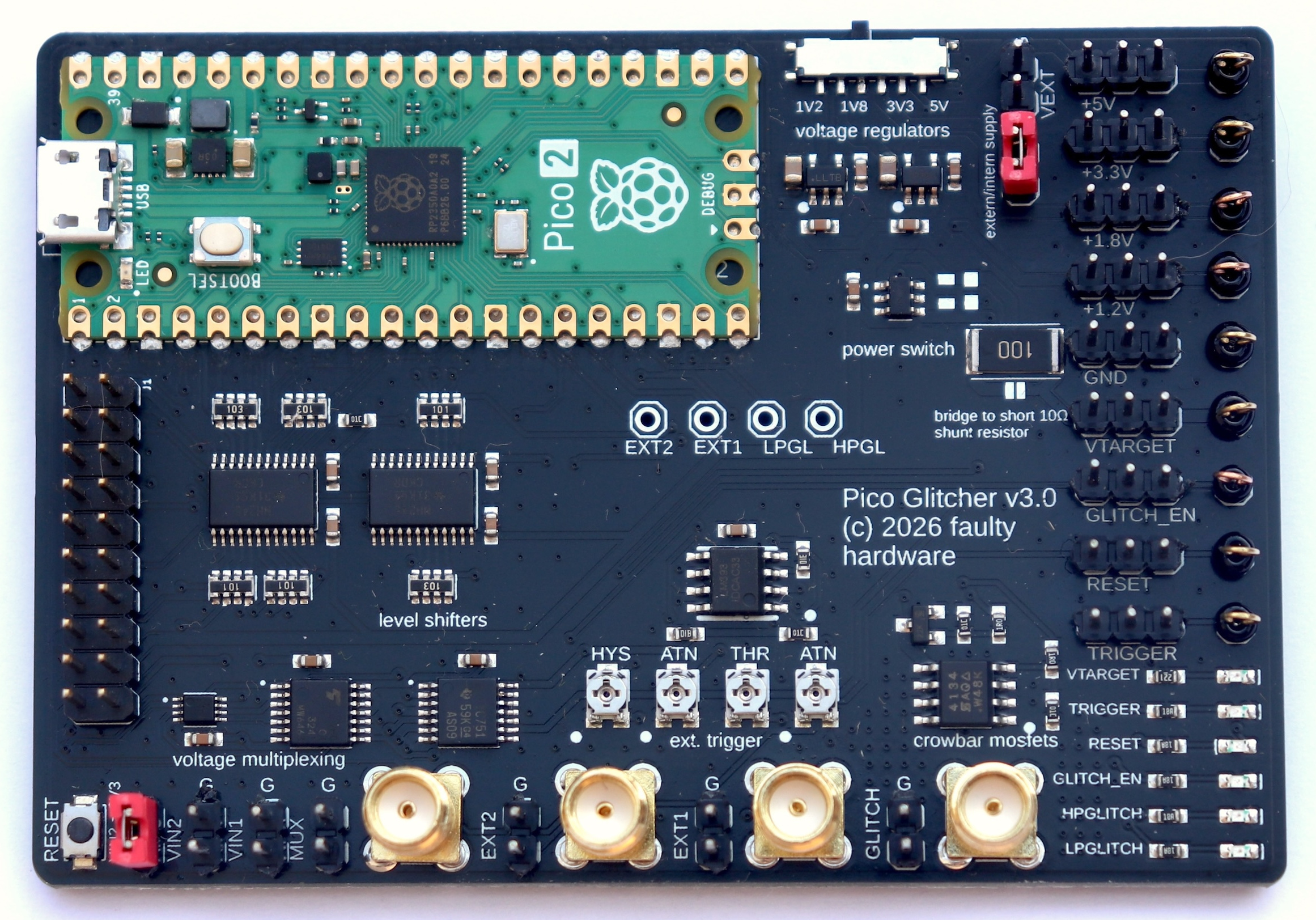
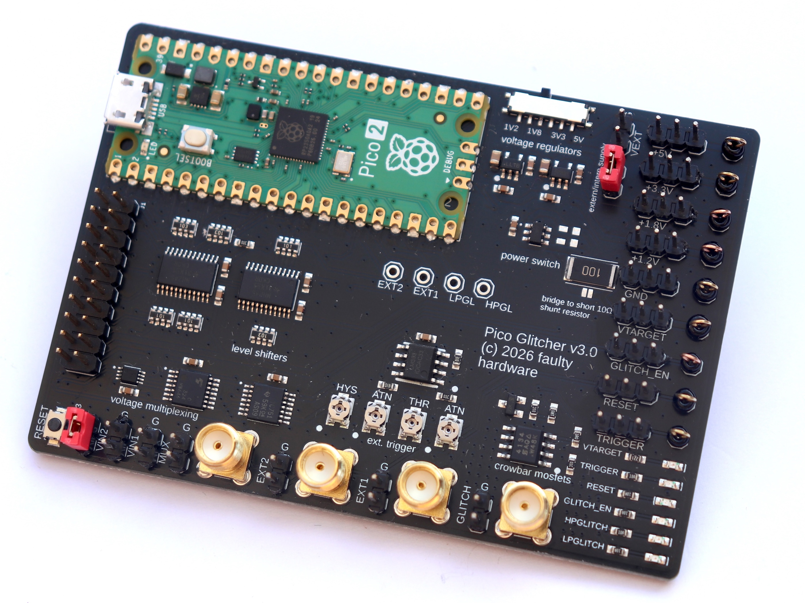
- The Pico Glitcher version 3 is based on the Raspberry Pi Pico 2: higher clock speed, better accuracy in glitching attacks, more power!
- Improved power supply: You can now choose from four different voltages to interface with various microcontrollers: 1.2V, 1.8V, 3.3V, and 5V.
- Improved Schmitt trigger inputs provide even better and more reliable triggering.
Everything else is unchanged: Two high-power MOSFETs for crowbar glitch generation, and two level shifters to ensure compatibility over a wide voltage range. An Schmitt Trigger input stage (EXT1 and EXT2) can be used to filter out noise and other disturbances via adjustable Schmitt Triggers. The multiplexing output can be used to quickly switch between up to four different voltage levels and to supply the target board with power.
Upgrade to the Raspberry Pi Pico 2
Compared to the original Raspberry Pi Pico, the Pico 2 is simply a better platform for voltage glitching. The most obvious advantage is performance. The Pico 2 runs at a significantly higher clock speed, which directly improves timing resolution. In glitching attacks, timing is everything. Finer timing granularity means you can place glitches more precisely relative to the target's execution, which increases both reliability and repeatability. To improve timing precision, for example, the clock speed of the Pico Glitcher can be increased by this code:
glitcher.set_cpu_frequency(300_000_000)
The Pico 2 also has a more capable microcontroller core and a faster peripheral subsystem. This reduces internal latency and jitter when generating glitch pulses or coordinating trigger events. On the Pico 1, software and peripheral delays can blur timing edges. On the Pico 2, those edges are sharper and more predictable, which translates into cleaner and more consistent glitches.
Memory and DMA improvements further help with complex glitching setups. The Pico 2 can handle tighter loops, faster state machines, and higher-rate signal generation without starving the CPU or missing critical timing windows. This matters when combining voltage glitches with precise triggers, delays, or pattern-based attacks.
Finally, the Pico 2 offers more overall headroom. Higher performance means you can push glitch widths shorter, offsets finer, and repetition rates higher before hitting architectural limits. In practice, this gives you more usable attack surface and less time fighting the tool itself.
In short, the Pico 2 is not just a minor upgrade. For voltage glitching, it delivers better timing accuracy, lower jitter, and more control, all of which directly improve attack success.
Improved Power Supply
The improved power supply makes the Pico Glitcher far more flexible when attacking real-world targets. Modern microcontrollers operate at a wide range of core and I/O voltages, and voltage glitching is most effective when the glitch amplitude closely matches the target's supply rail. By supporting 1.2 V and 1.8 V directly, the Pico Glitcher can interface cleanly with low-power and high-performance MCUs without level shifters or external regulators.
Having native support for 3.3 V and 5 V also simplifies working with older or more traditional designs. The ability to select the correct voltage reduces the risk of over- or under-driving the target, which can otherwise lead to unstable behavior, resets, or permanent damage instead of controlled faults.
From a glitching perspective, selectable supply voltages give finer control over fault injection. Matching the nominal supply voltage allows smaller, more precise voltage drops during a glitch, increasing the chance of inducing subtle logic errors rather than full system crashes. This results in more reproducible faults and a higher success rate during attacks.
Overall, the multi-voltage power supply removes guesswork and external hardware from the setup. It lets you adapt quickly to different targets, tune glitch parameters more accurately, and focus on the attack instead of power management.
Improved Schmitt Trigger inputs
The trigger inputs EXT1 and EXT2 are particularly useful for noisy logic signals, as the noise can be easily suppressed by the adjustable Schmitt Trigger. If, for example, the signal oscillates or is disturbed in any other way, this disturbances can be cut off by selecting a suitable threshold.
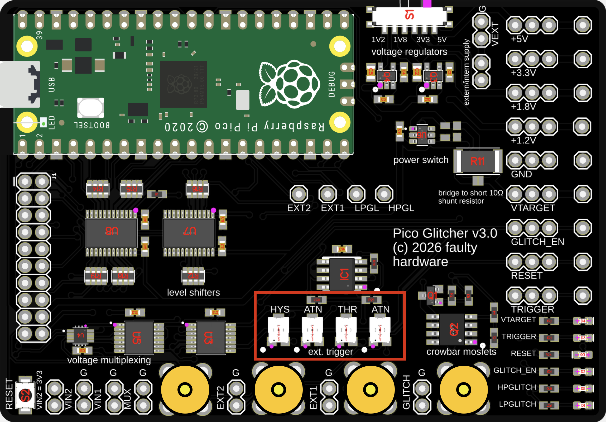
Use the potentiometer labeled THR to adjust the threshold of the Schmitt Trigger. The threshold is lowered by turning the potentiometer to the left.
The potentiometer ATN can be used for an additionally signal reduction, if necessary. Turning the potentiometer all the way to the right disables attenuation and uses the full signal range.
The HYS potentiometer is used to adjust the hysteresis of the Schmitt trigger input EXT2. It controls the difference between the upper and lower switching thresholds. By changing this difference, it directly determines how much the input signal must move before the output changes state.
With no hysteresis, the Schmitt trigger switches at the same input level for both rising and falling edges. The output changes state exactly at a single threshold, making the circuit sensitive to noise and small fluctuations around that level.
When hysteresis is introduced, the switching point depends on the direction of the input signal. On a rising input, the signal must reach the upper threshold before the output changes, causing the transition to occur later than it would without hysteresis. On a falling input, the signal must drop below the lower threshold before switching back, which also delays the transition compared to a single-threshold comparator.
Increasing the hysteresis widens the gap between the upper and lower thresholds. This makes the circuit switch later on both rising and falling edges, relative to the no-hysteresis case. Reducing the hysteresis narrows this gap, bringing the two switching points closer together until they coincide when hysteresis is effectively zero.
This behavior is what gives the Schmitt trigger its noise immunity: small variations around the switching level do not cause repeated transitions, and the exact timing of state changes can be deliberately shifted by adjusting the hysteresis.
Continue reading
Continue reading about the Pico Glitcher and its capabilities, or how to attack various microcontrollers, here:
- The beginning of the Pico Glitcher
- The Pico Glitcher v2
- The Pico Glitcher v3
- Voltage multiplexing and parameter optimization
- Attacking the STM32F4 with the PicoGlitcher
- Attacking the Trezor One Crypto Wallet (new firmware)
- Glitching the Raspberry Pico with a Raspberry Pico
- Attacking the SMT32L051 with the Pico Glitcher
- Attacking the nRF54L15 with an Electromagnetic Fault Injection (EMFI) attack and the Pico Glitcher
- Voltage Glitching with the Pico Glitcher and Findus
- The Pico Glitcher on Youtube